3D motion recognition method and apparatus

Inactive Publication Date: 2012-06-14
ELECTRONICS & TELECOMM RES INST
View PDF0 Cites 40 Cited by
  • Summary
  • Abstract
  • Description
  • Claims
  • Application Information

AI Technical Summary

Benefits of technology

[0006]The present disclosure has been made in an effort to provide a feature-based stereo matching method that is free of the above-mentioned conditions assumed by an area-based method and may rapidly create a more accurate depth map by using minimum information without performing a calibration process for obtaining an epi-polar line.
[0010]The comparing of the feature points includes gradually reducing a resolution of the obtained image to create multiple levels of resolution and performing comparison from an image having the lowest resolution.
[0019]The feature point comparing and extracting unit removes noise by using a motion template method in which an area that has movement is represented by a bright color and an area that does not have movement is represented by a dark color.
[0020]According to the exemplary embodiments of the present disclosure, the feature-based stereo matching method is performed by using the optical flow method for the space rather than the time, such that it is not required to find the epi-polar line through a difficult calibration process and to perform rectification.
[0021]Further, even though the binocular color senses or brightness values are slightly different, features of both images may be accurately and stably tracked. Therefore, it is possible to directly perform stereo vision without conducting any adjustment process in a state in which two web cameras are disposed in parallel with each other.
[0022]In addition, since a performing speed is processed in real time, the present disclosure may be easily applied to several real-time applications.

Problems solved by technology

The feature-based method may be relatively free of several restrictions of the area-based method and may generate a more accurate and robust depth map, but has a limitation in generating a relatively sparse depth map.
However, the area-based method always needs a calibration process that matches an epi-polar line and needs calculation time longer than the feature-based method because it needs to calculate the depth value for the entire area of an image.

Method used


Image

  • 3D motion recognition method and apparatus
  • 3D motion recognition method and apparatus
  • 3D motion recognition method and apparatus

Examples


Embodiment Construction

[0032]In the following detailed description, reference is made to the accompanying drawing, which form a part hereof. The illustrative embodiments described in the detailed description, drawing, and claims are not meant to be limiting. Other embodiments may be utilized, and other changes may be made, without departing from the spirit or scope of the subject matter presented here.

[0033]Hereinafter, exemplary embodiments of the present disclosure will be described in detail with reference to the accompanying drawings.

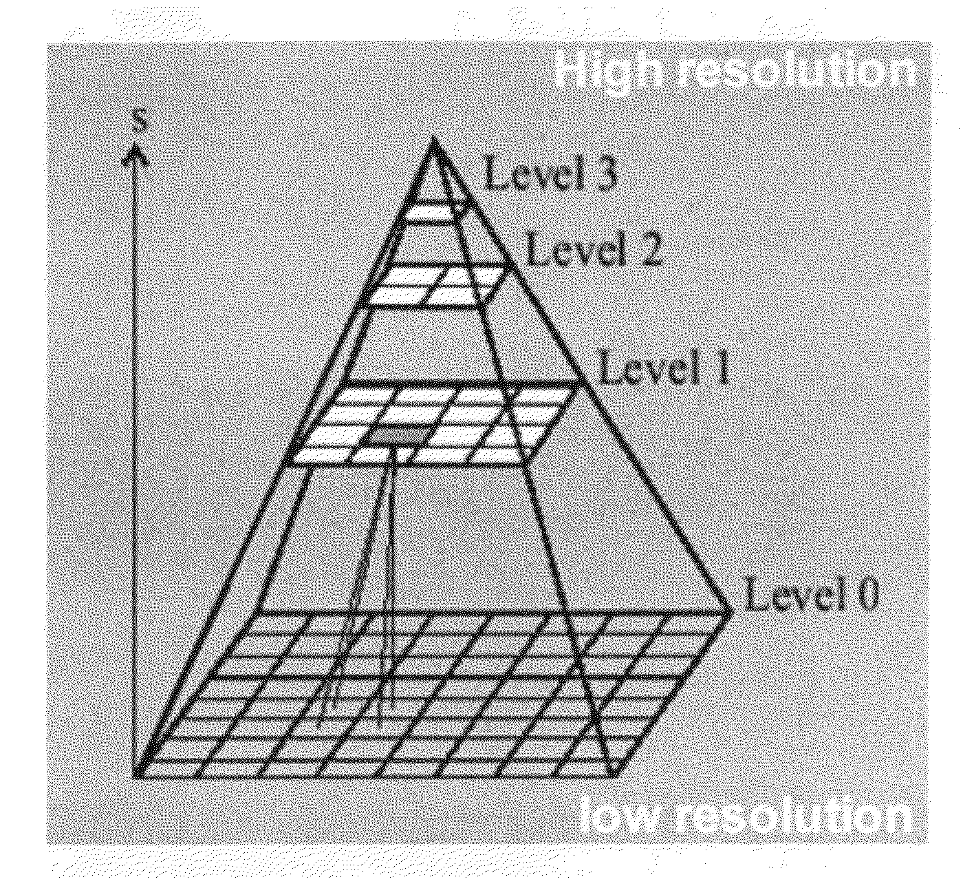
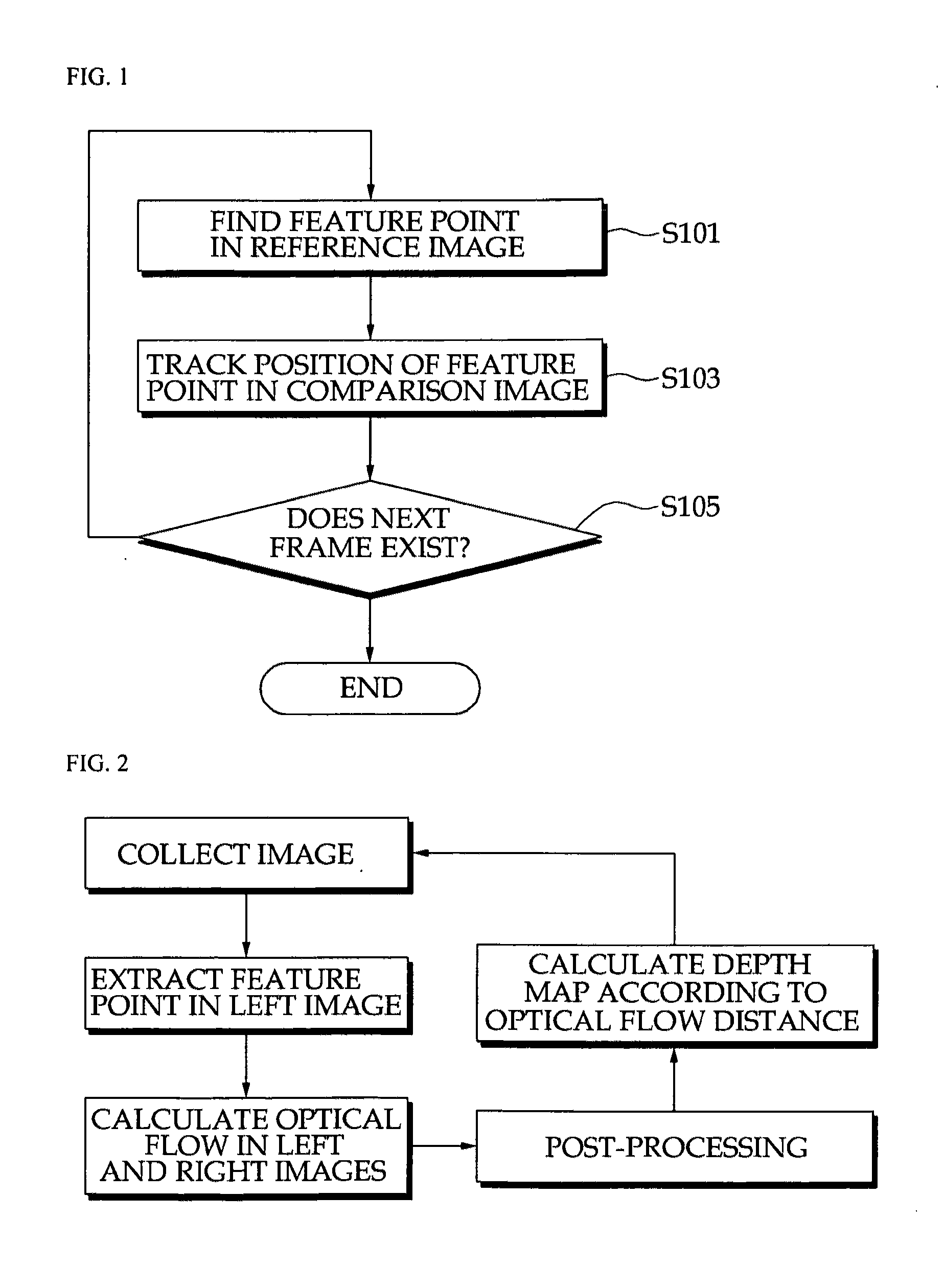
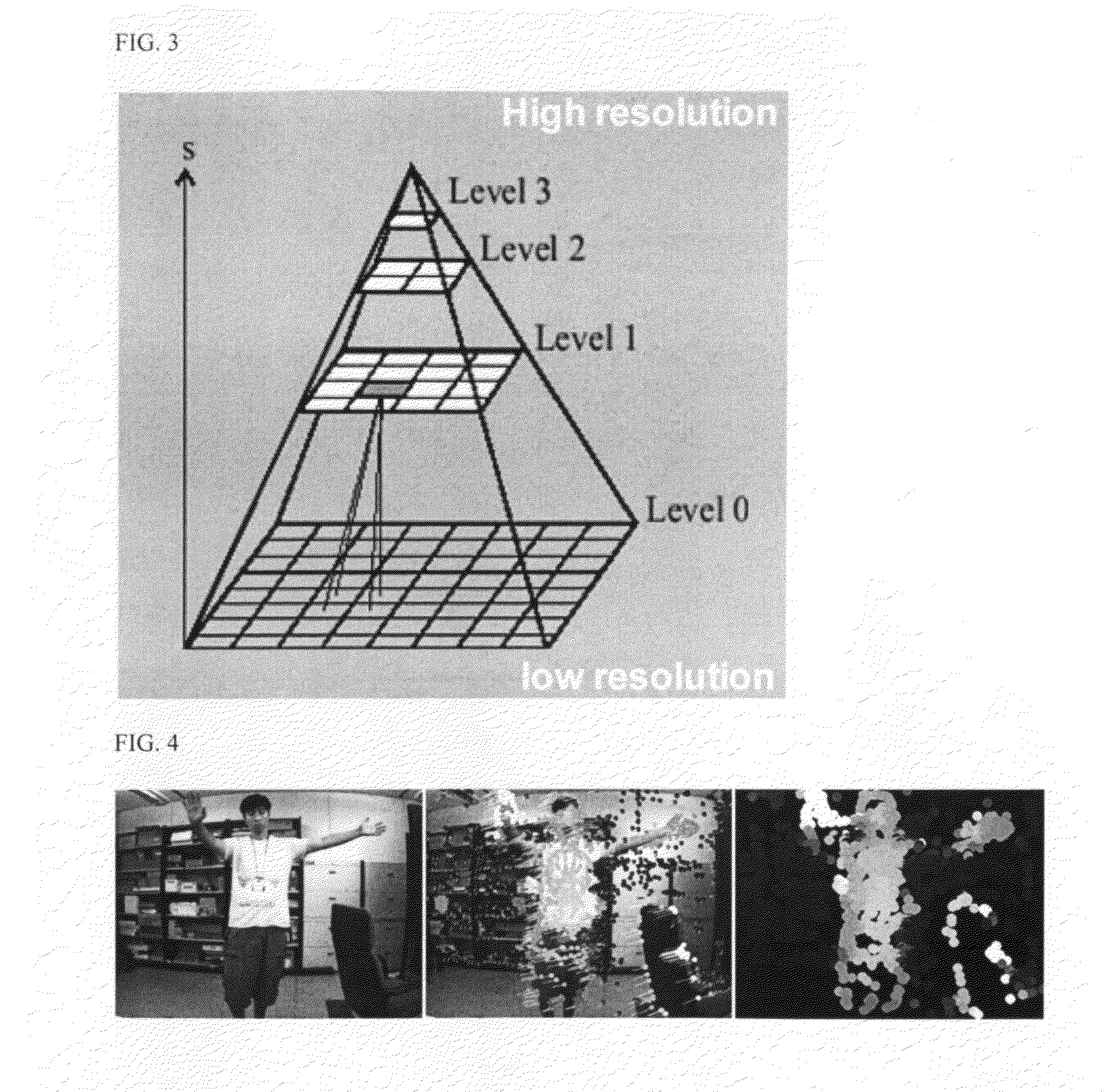
[0034]A stereo matching method using an optical flow tracking method of feature points according to an exemplary embodiment of the present disclosure does not obtain an epi-polar line. Therefore, it is not required to control several complicated software and hardware in order to perform calibration. In addition, color senses or brightness values of images photographed in both eyes need not to coincide with each other. Since the stereo matching method according to the exem...


PUM


Abstract

Disclosed are a three-dimensional motion recognition method and an apparatus using a motion template method and an optical flow tracking method of feature points. The three dimensional (3D) motion recognition method through feature-based stereo matching according to an exemplary embodiment of the present disclosure includes: obtaining a plurality of images from a plurality of cameras; extracting feature points from a single reference image; and comparing and tracking the feature points of the reference image and another comparison image photographed at the same time using an optical flow method.

Description

CROSS-REFERENCE TO RELATED APPLICATIONS[0001]This application is based on and claims priority from Korean Patent Application No. 10-2010-0127564, filed on Dec. 14, 2010, with the Korean Intellectual Property Office, the present disclosure of which is incorporated herein in its entirety by reference.TECHNICAL FIELD[0002]The present disclosure relates to a three-dimensional motion recognition method and apparatus using a stereo matching method. More particularly, the present disclosure relates to a feature-based stereo matching method and apparatus capable of finding feature points in a reference image and tracking the same locations in comparison images to obtain binocular disparity.BACKGROUND[0003]Generally, stereo matching means obtaining an accurate and reliable disparity map by estimating disparity between corresponding points between two images obtained at different viewpoints by using the same method as a method of recognizing a distance of an object through two human eyes.[000...

Claims


Application Information

Patent Timeline
IPC IPC(8): G06K9/62
CPCG06K9/00335G06T7/0075G06T7/2073G06T2207/30196G06T2207/10021G06T2207/20016G06T7/2086G06T7/593G06T7/207G06T7/285G06V40/20
Inventor PARK, JUN SEOKKOH, EUNJIN
Owner ELECTRONICS & TELECOMM RES INST
Why Eureka
Try Eureka