Image heating apparatus

a heating apparatus and image technology, applied in the field of image heating apparatus, can solve the problems of scarring and/or serious very rapid start-up, and easy damage to the fixation belt and/or pressure roller, so as to prevent the weight of the member

Inactive Publication Date: 2012-06-14
CANON KK
View PDF11 Cites 15 Cited by
  • Summary
  • Abstract
  • Description
  • Claims
  • Application Information

AI Technical Summary

Benefits of technology

[0011]Thus, the primary object of the present invention is to provide an image heating apparatus, which has a mechanism for preventing the weight of the member for heating the rotational heating member by electromagnetic induction, and the weight of the rotational heating member itself, from resting on the fixation nip of the apparatus, after the removal of the pressure from the fixation pressure application spring from the fixation nip, being therefore far superior to an image heating apparatus in accordance with the prior art, which employs a rotational fixing member heatable by electromagnetic induction, in terms of the easiness and efficiency with which a jammed sheet can be removed.

Problems solved by technology

Thus, it starts up very quickly.
If an attempt is made to remove the jammed sheet or sheets of recording medium from a fixing apparatus of this type while its fixation belt is still kept pressed upon the pressure roller, the sheet removing operation becomes very troublesome and irritating.
Further, an attempt to forcefully pull out the jammed sheet is likely to scar and / or seriously damage the fixation belt and / or pressure roller.
However, the weight of the fixation belt unit has virtually no effect upon the operation for removing the jammed paper.
Thus, even after the removal of the pressure from the pressure application spring, the job for removing a jammed sheet of recording medium is still irritating and time consuming.

Method used


Image

  • Image heating apparatus
  • Image heating apparatus
  • Image heating apparatus

Examples


embodiment 1

(Image Forming Apparatus)

[0031]FIG. 3 is a schematic sectional view of the image forming apparatus in the first preferred embodiment of the present invention, which employs an image heating apparatus in accordance with the present invention, as its fixing device, at a plane parallel to the recording medium conveyance direction of the apparatus. More concretely, the image forming apparatus in this embodiment is a color printer, which uses an electrophotographic process. It has multiple (four) optical scanning means and multiple (four) photosensitive drums. The four drums are aligned in tandem and are in parallel to each other. It has also an image reader 200 which obtains from a full-color original image, the information necessary to form a copy of the original. That is, it separates an original full-color image into four monochromatic images which are different in color, with the use of its photo-electric conversion element, such as a CCD. The image reader is on top of the main asse...

embodiment 2

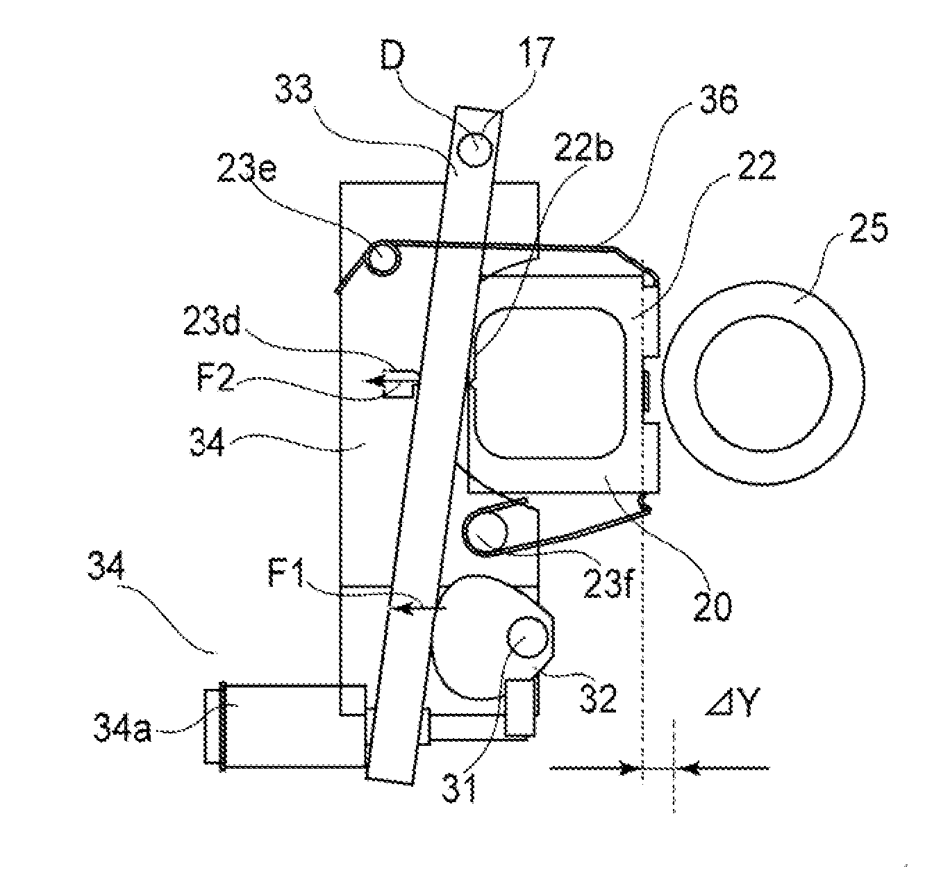
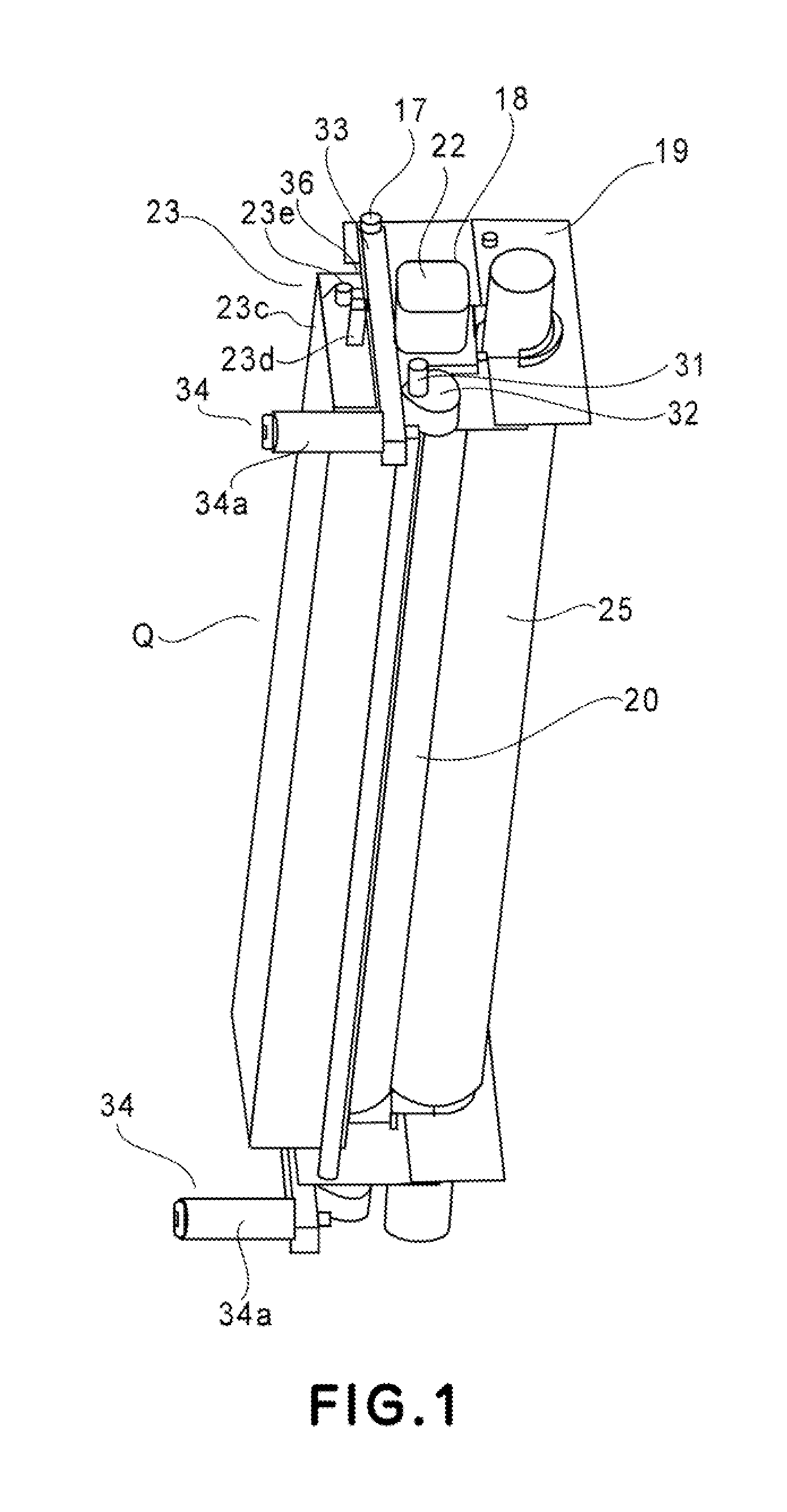
[0071]FIGS. 7-11 are for describing the fixing device in the second preferred embodiment. The fixing device in this embodiment employs a toggle as a means for keeping the induction heating unit 23 and fixation belt unit 20 fastened to each other.

(Structure of Toggle)

[0072]A toggle is a mechanism made up of a pair of jointed arms (links) and a slider. The force to be inputted into the mechanism is transmitted through a linkage. As the force is inputted, the pair of jointed arms moved toward the direction from which the force is inputted, until the jointed arms lock themselves with the objects, such as a wall, around them. Once the jointed arms lock themselves with the surrounding objects, they do not move backward, anchoring the mechanism against the external force which is opposite in direction from the input force.

[0073]The toggle in this embodiment has a lever 37 and a spring 38. The lever 37 corresponds to the pressure application lever 33 in the first embodiment. The toggle is a...

embodiment 3

[0085]FIG. 12 is a schematic sectional view of the fixing device in the third preferred embodiment of the present invention, at a plane parallel to the recording medium conveyance direction. This embodiment is different from the first embodiment in that the fixing device in this embodiment has a recording medium guide 27 for separating a sheet P of recording medium from the fixation belt 21. Hereafter, this guide 27 is referred to as a separation guide 27. Otherwise, this embodiment is the same as the first embodiment. That is, the fixation belt unit and induction heating of the fixing device themselves in this embodiment are the same in structure as the counterparts in the first embodiment, and the fixing operation of the fixing device in this embodiment is the same as that in the first embodiment. Therefore, they are not going to be described here.

(Separation Guide)

[0086]The fixing device in this embodiment is provided with at least one separation guide 27 for separating a sheet o...


PUM


Abstract

An image heating apparatus includes a heating unit including a rotatable image heating member; an induction heating unit for externally induction heating the image heating member; a nip forming member press-contacting an outer surface of the image heating member to form a nip therewith; a pressing member for pressing the heating unit to the nip forming member; a press releasing member for releasing a pressure of the pressing member to the heating unit; fastening means for fastening the heating unit and the induction heating unit together; and a force receiving portion, provided on the induction heating unit, for contacting the pressing member to move the heating unit away from the nip forming member when the press releasing member releases the heating unit from the pressure of the pressing member.

Description

FIELD OF THE INVENTION AND RELATED ART[0001]The present invention relates to an image heating apparatus mountable in an image forming apparatus such as an electrophotographic copying machine, an electrophotographic printer, and the like.[0002]There have been known various fixing apparatuses (fixing devices) mountable in an electrophotographic copying machine, an electrophotographic printer, and the like. One of them has been known as a fixing apparatus of the belt heating type, that is, a fixing apparatus which heats an image with the use of a fixation belt. A fixing apparatus of this type is small in thermal capacity, and also, high in heat transmission efficiency. Thus, it starts up very quickly. Therefore, it has been known as a fixing apparatus of the on-demand type.[0003]One of the fixing devices which use a fixation belt is disclosed in Japanese Laid-open Patent Application 2002-268414. This fixing device has: a heat generating member, for example, a ceramic heater (which here...

Claims


Application Information

Patent Timeline
Patent Type & Authority Applications(United States)
IPC IPC(8): G03G15/20
CPCG03G15/2053
Inventor SUGAYA, KENJIROUWATANABE, TATSUHITO
Owner CANON KK
Why Eureka
Try Eureka