
Radiating device and speed regulator with same

A technology of heat sink and governor, which is applied in the modification of power electronics, cooling/ventilation/heating transformation, etc., can solve the problem of large plane area of ​​flat-panel radiator, simplify the process, reduce the volume, and facilitate disassembly and maintenance. Effect

Active Publication Date: 2011-11-09
YUNEEC TECH CO LTD +1
View PDF4 Cites 24 Cited by
  • Summary
  • Abstract
  • Description
  • Claims
  • Application Information

AI Technical Summary

Problems solved by technology

[0003] The technical problem to be solved by the present invention is to overcome the defect that the planar area of ​​the flat radiator of the existing governor is too large, and to provide a cooling device that can realize efficient centralized heat dissipation without increasing the weight of the governor and its the governor

Method used


Image

  • Radiating device and speed regulator with same
  • Radiating device and speed regulator with same
  • Radiating device and speed regulator with same

Examples


Embodiment 1

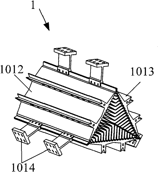
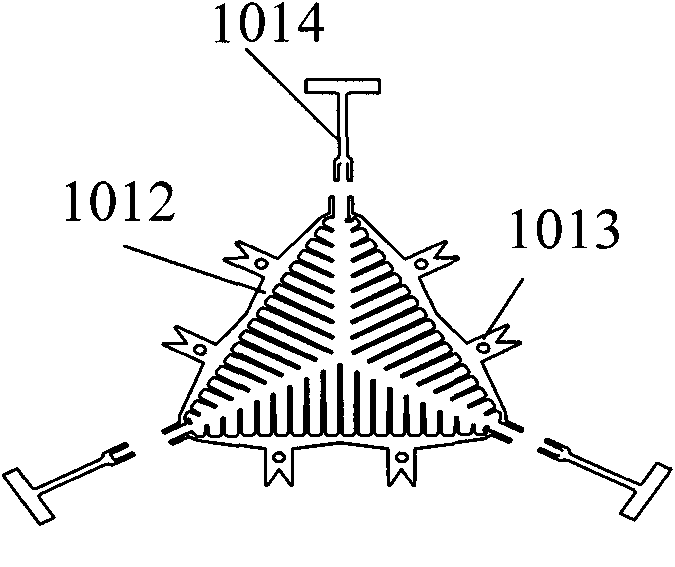
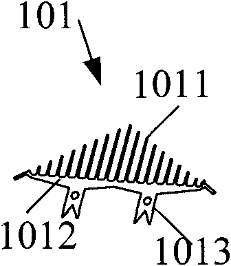
[0038] Figure 1 to Figure 6 As shown, it is an embodiment of a heat dissipation device 1 with a triangular ventilation section provided by the present invention. The heat dissipation device 1 is assembled from three identical heat dissipation units 101 , and the heat dissipation device 1 is in the shape of a triangular prism. The heat dissipation plate 1012 of each heat dissipation unit 101 forms each facet of the triangular prism, and the plurality of heat dissipation ribs 1011 on the heat dissipation unit 101 are ridge-shaped protrusions, and the lengths are orderly, and the heat dissipation ribs 1011 distributed on the three heat dissipation units 101 are The alternate butt joints form a heat dissipation layer for the heat dissipation device 1 to dissipate heat from inside to outside.

[0039] In order to install and fix the heat dissipation device 1 on the circuit board 2 , two bone positions 1013 are arranged at intervals on each heat dissipation plate 1012 of the heat ...

Embodiment 2

[0041] Based on the heat dissipation device of Embodiment 1, the present invention also provides the following governor.

[0042] Such as figure 1 with Image 6 As shown, the three circuit boards 2 of the governor are electrically connected to each other, and are fixedly connected to the heat dissipation device 1 through the bone 1013 on the heat dissipation plate 1012 of each heat dissipation unit 101 . The governor is provided with a power input terminal 8 and three power output terminals 9 , and a plurality of electronic components, such as heating power devices 201 , are arranged on the circuit board 2 .

[0043] The heating power device can be a MOSFET tube (Metal-Oxide-Semiconductor Field-Effect Transistor, Metal-Oxide-Semiconductor-Field-Effect Transistor, referred to as Metal-Oxide-Semiconductor Field-Effect Transistor). Nearly thirty-two MOSFET tubes and six capacitors are arranged on each circuit board 2 in this embodiment. Every two circuit boards 2 are electrica...


PUM


Abstract

The invention discloses a radiating device. The radiating device is a poly-prismoid formed by assembling a plurality of radiating units and is provided with a corresponding polygonal ventilating section; and a radiating layer for radiating from the center to the periphery is formed in the radiating device. The radiating device provided by the invention integrates multiple plates, three surfaces of the radiating device are provided with a printed circuit board (PCB) respectively, and the heat of all the PCBs does not influence one another in a same space; due to the integration of multiple plates, the length of the conventional PCB is reduced to 1 / 3 of that of the conventional design; and the difficulties in weight, space, cooling and radiation of a speed regulator are overcome more effectively.

Description

technical field [0001] The invention relates to a heat dissipation structure and a speed governor, in particular to a heat dissipation device capable of dissipating heat from inside to outside and a speed governor using the heat dissipation device. Background technique [0002] The existing speed governor controls the speed of the motor through the circuit board on it. There are high-power switching devices installed on the circuit board, and these high-power switching devices will generate a lot of heat when they work. If the generated heat is not dissipated in time, the heat-generating power devices will enter a vicious circle and eventually burn out the power devices. Therefore, it is necessary to dissipate heat from the governor in time. Existing governors usually dissipate heat by adding aluminum strips to the heat-generating power devices. When the power of the motor increases, the number of power tubes also increases. In order to dissipate heat, more aluminum stri...

Claims


Application Information

Patent Timeline
IPC IPC(8): H05K7/20
CPCH05K7/20918
Inventor 田瑜江文彦
Owner YUNEEC TECH CO LTD
Learn More