Clamp mounting system

a technology of mounting brackets and clamps, which is applied in the direction of manufacturing tools, metal-working machine components, transportation and packaging, etc., can solve the problems of assembly time, and increasing the cost of parts. , to achieve the effect of reducing the obstruction of optical sensing and workpieces, part weight and assembly time, and reducing the cost of parts

Active Publication Date: 2014-04-17
BTM COMPANY
View PDF5 Cites 24 Cited by
  • Summary
  • Abstract
  • Description
  • Claims
  • Application Information

AI Technical Summary

Benefits of technology

[0004]The present clamp mounting system is advantageous over conventional approaches since the present system does not require additional mounting brackets. Furthermore, the single mounting plate per structural riser allows for side or bottom mounting along vertical or horizontal datum surfaces. Additionally, the present system advantageously tightly fastens the clamp assembly against the mounting plate side walls with a single diagonal fastener, with optional shims in between. The generally symmetrical design of the clamp body allows for different clamp orientations relative to the mounting plate and structural datum, which provides for greater locational flexibility and reduced obstruction for optical sensing and workpieces during clamp alignment and clamping usage. Moreover, the present clamp mounting system reduces part costs, part weight and assembly time. Additional advantages and features of the present invention can be ascertained from the following description and claims as well as the appended drawings.BRIEF DESCRIPTION OF THE DRAWINGS
[0027]A similar arrangement is employed for the vertically oriented datum surface 33 and clamp assembly 31 shown in FIGS. 8-10. In this configuration, however, the generally cube-shaped configuration of clamp body 65 allows it to be mounted on a different side than that for the horizontal datum surface mounting of FIG. 3. It is noteworthy that only a single mount 41 and set of shims are needed in order to precisely align and secure a clamp to a structural datum member, thereby avoiding the extra expense, weight and setup time required for conventional supplemental bracketry and fasteners.

Problems solved by technology

Conventional mounting and alignment of such clamps is time consuming and expensive.
Furthermore, these traditional clamps are often difficult to place in differing orientations relative to the riser.
Since many pin clamps are used on each assembly plant trolley or moving pallet, these extra mounting brackets collectively add considerable weight, part cost and set up time.

Method used


Image

  • Clamp mounting system
  • Clamp mounting system
  • Clamp mounting system

Examples


Embodiment Construction

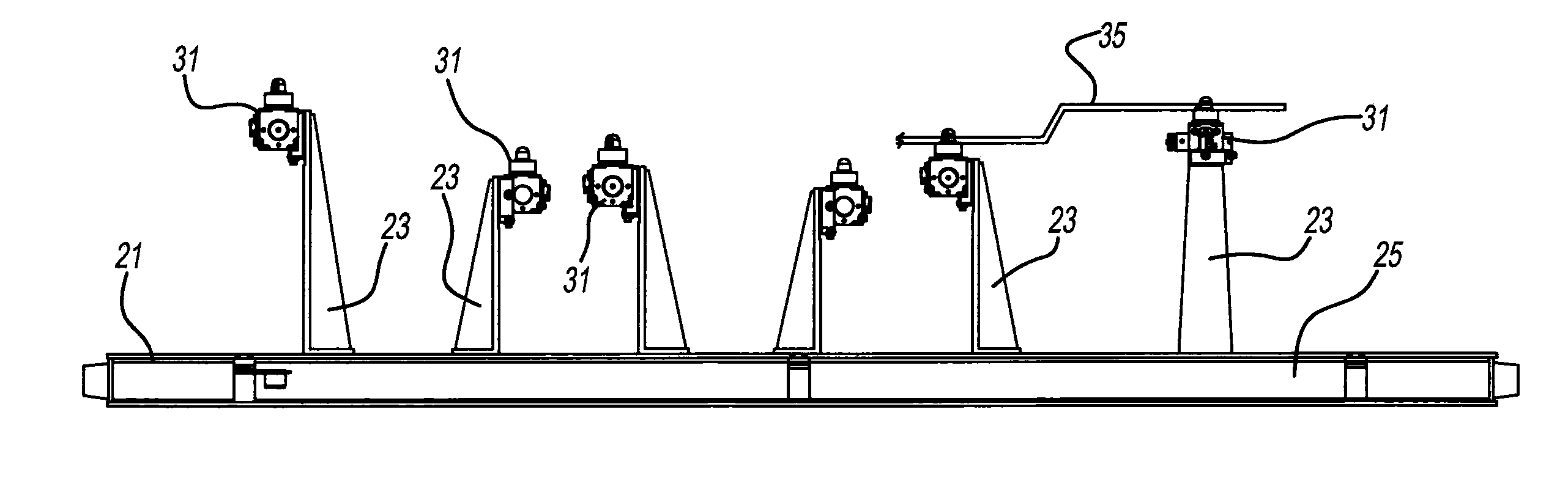
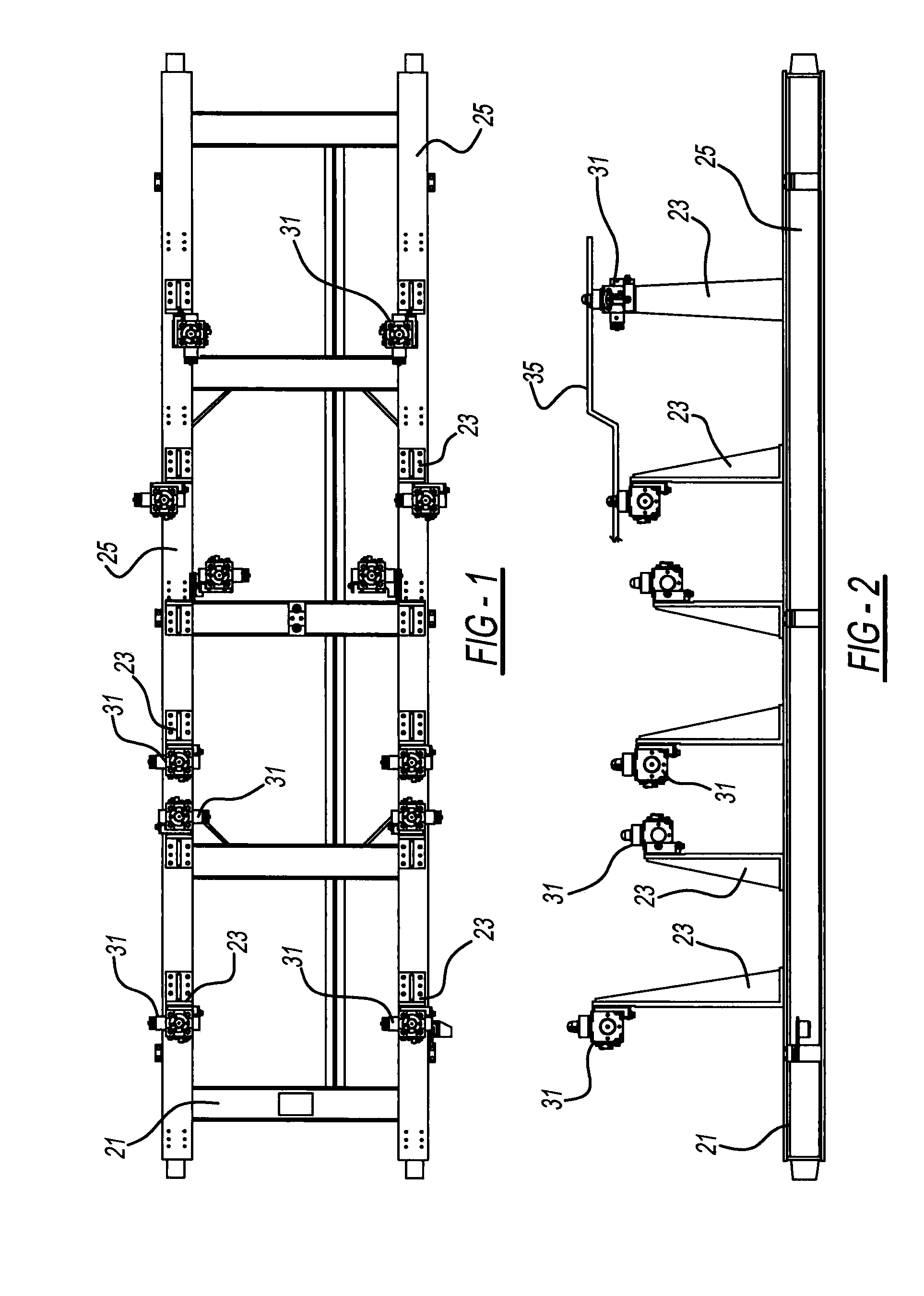
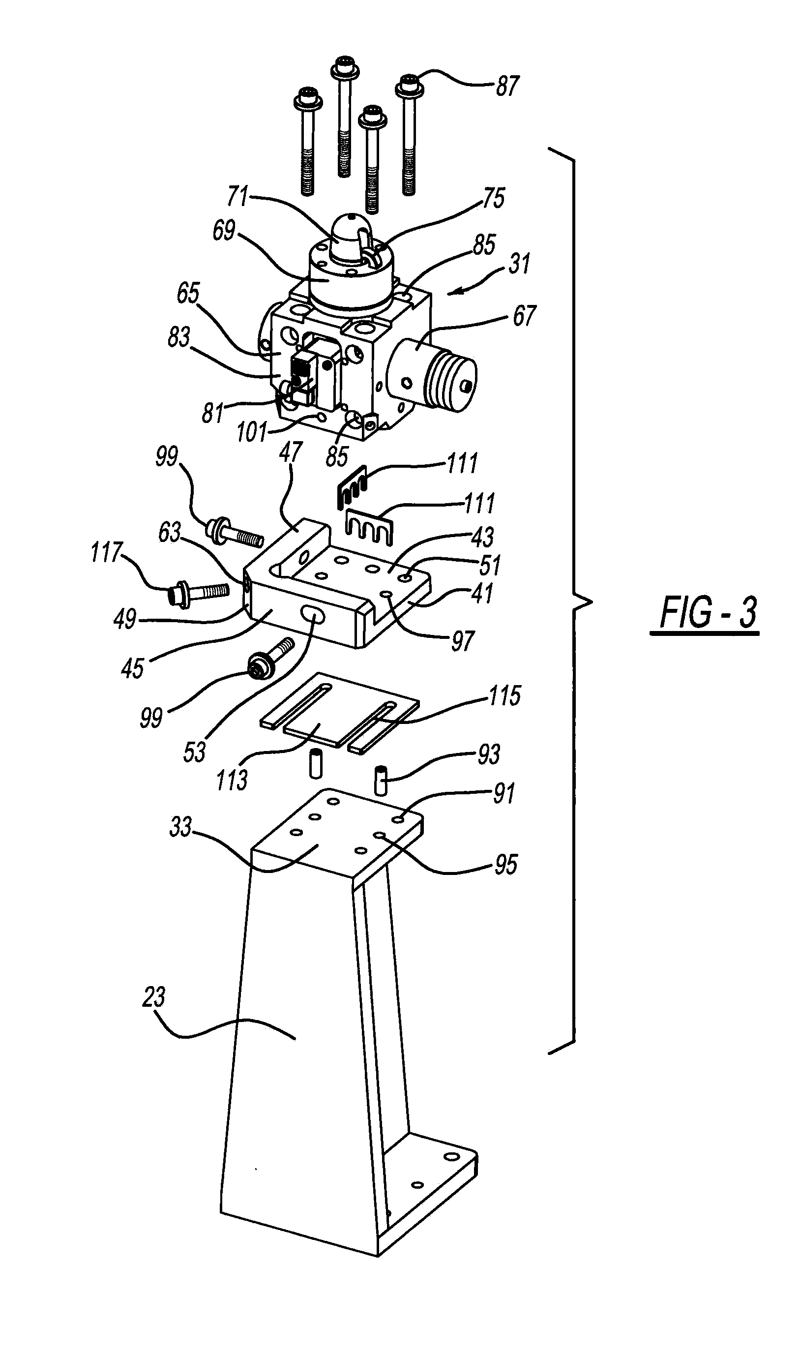
[0021]Referring to FIGS. 1, 2, 3 and 8 a trolley 21, also known as a conveyor cart or pallet, is attached to and automatically moves along an assembly line in an automotive vehicle assembly plant. A plurality of upstanding structural risers, pillars or locators 23 are fixed to underlying horizontal beams 25 of each trolley 21. A mounting system attaches each pin clamp assembly 31 to a datum surface 33 of each riser 23. Each pin clamp serves to align and temporarily secure sheet metal automotive vehicle panels or workpieces 35 for movement with each trolley 21 as it moves from a loading station, to a welding or riveting station, and then to an unloading station. Risers 23 are illustrated as having either a horizontal datum surface, as shown in FIG. 3, or having a vertical datum surface, as shown in FIG. 8, however, diagonally angled or other orientations may be alternately provided for this datum surface which acts as a reference plane for alignment and mounting of pin clamp assembly...


PUM

PropertyMeasurementUnit
distanceaaaaaaaaaa
thickaaaaaaaaaa
distanceaaaaaaaaaa

Abstract

A single mounting device is provided for each trolley riser for use with a set of shims in order to accurately align and secure a clamp to a datum. In another aspect, a generally polyhedron-shaped clamp body is used with a mounting plate to secure a clamp in different orientations relative to a manufacturing plant locator.

Description

BACKGROUND AND SUMMARY[0001]The invention generally pertains to a workpiece retaining clamp and more particularly to a clamp mounting system.[0002]Various locking pin clamps have been used for vehicular assembly. Exemplary conventional constructions are disclosed in the following U.S. Pat. No. 8,001,673 entitled “Clamping Device for Vehicle Body Transfer Cart” which issued to Hur on Aug. 23, 2011; U.S. Pat. No. 7,469,473 entitled “Assembly Line Vehicle Body Positioning” which issued to Savoy on Dec. 30, 2008; and U.S. Pat. No. 6,687,971 entitled “Vehicle Body Transfer Machine and Method Thereof” which issued to Nakamura on Feb. 10, 2004. Another tradition example is disclosed in U.S. Patent Publication No. 2012 / 0030924 entitled “Vehicular Body Assembly Locking Apparatus and Method” which published to Kilibarda et al. on Feb. 9, 2012. These patents and application are all incorporated by reference herein. Conventional mounting and alignment of such clamps is time consuming and expens...

Claims


Application Information

Patent Timeline
Patent Type & Authority Applications(United States)
IPC IPC(8): B23P11/00B23Q1/25
CPCB62D65/18B25B5/003B25B5/006B25B5/087B62D65/026Y10T29/49826B23Q1/26B23Q3/08
Inventor PETIT, BRIAN D.SANDERS, ANDREW T.
Owner BTM COMPANY
Why Eureka
Try Eureka