Centrifugal compressor
- Summary
- Abstract
- Description
- Claims
- Application Information
AI Technical Summary
Benefits of technology
Problems solved by technology
Method used
Image

Examples
first embodiment
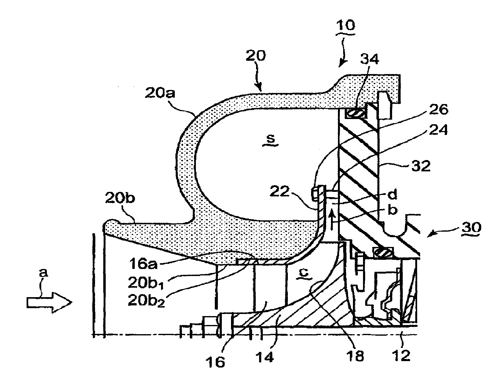
[0045]A first embodiment of a centrifugal compressor to which the present invention is applied is explained in reference to FIG. 1. In FIG. 1, a rotating shaft 12 is arranged in a center of a resin housing 20, and an impeller 14 having a plurality of blades 16 fixed radially is fixed to an outer periphery of the rotating shaft 12. A hub face 18 of the impeller 14 curves from an inlet side to an outlet side in a flow direction of a gas to be compressed (a direction indicated with an arrow a) from an axial direction to a radial direction of the rotating shaft 12. The resin housing 20 includes a volute section 20a which forms a volute part s and a path forming section 20b which forms a flow path c for the gas to be compressed.
[0046]The outer edge of the blade forms a curved profile 16a. Along the curved profile 16a, an inner wall 20b1 of the path forming section 20b of the resin housing 20 is formed. The inner wall 20b1 is carved to form a depression 20b2 in which an annular shroud is ...
second embodiment
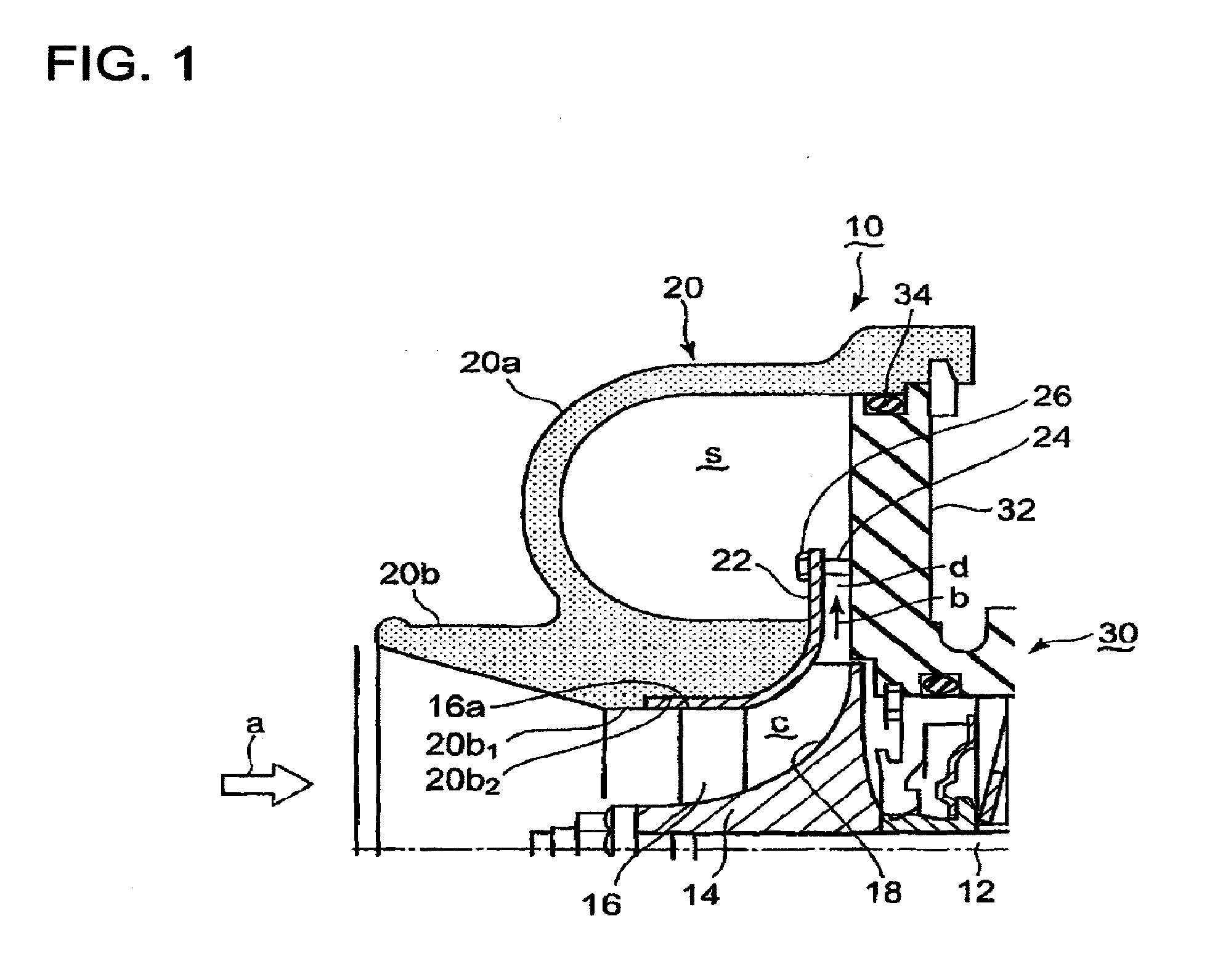
[0052]A second embodiment of the centrifugal compressor to which the present invention is applied is explained in reference to FIG. 2. In the second embodiment, as shown in FIG. 2, the downstream end 22a of the annular shroud 22 has two bending sections. The annular shroud 22 bends at a first bending section to extend to a position where the downstream end comes in contact with the wall 32 of the bearing housing 30 and bends at a second bending section to form a flange part 22a1. The wall 32 is formed with a depression 32a in which the flange part 22a1 is fitted. The flange part 22a1 is connected to the depression 32a by a bolt 40.
[0053]The flange part 22a1 is formed partially around the impeller 14. Thus, the downstream end 22a of the shroud 22 does not block the diffuser d or interfere with the flow of the gas in the diffuser. The rest of the structure is substantially the same as that of the first embodiment. The same parts are indicated by the same reference numerals.
[0054]Accor...
third embodiment
[0055]Next, a third embodiment in which the present invention is applied to a centrifugal compressor is explained in reference to FIG. 3. In the third embodiment, the depression 20b2 carved in the inner wall 20b1 of the path forming section 20b of the resin housing 20, is carved to form a groove 52. In the groove 52, a rubber or resin seal ring 50 is inserted. The rest of the structure is substantially the same as that of the second embodiment.
[0056]According to the third embodiment, even when the resin housing 20 thermally deforms, creating a gap between the depression 20b2 and a rear face of the annular shroud 22, it is possible to prevent the entry of the gas between the depression 20b2 and the annular shroud 22 by means of the seal ring 50. Therefore, the compression efficiency of the compressor does not decrease.
[0057]At an inlet of the impeller 14, the temperature of the gas is approximately the same as the ambient air and is low. At the inlet of the impeller, the temperatures...
PUM
 Abstract
Description
Claims
Application Information
 - Generate Ideas
- Intellectual Property
- Life Sciences
- Materials
- Tech Scout
- Unparalleled Data Quality
- Higher Quality Content
- 60% Fewer Hallucinations
Browse by: Latest US Patents, China's latest patents, Technical Efficacy Thesaurus, Application Domain, Technology Topic, Popular Technical Reports.
© 2025 PatSnap. All rights reserved.Legal|Privacy policy|Modern Slavery Act Transparency Statement|Sitemap|About US| Contact US: help@patsnap.com