Sports footwear

a technology of sports footwear and fixing elements, applied in the field of footwear, can solve the problems of user-specific characteristics, reducing the useful life of the boot, and wear of the fixing element, and achieve the effects of extending the useful life, ensuring safety, and satisfying the steering precision

Inactive Publication Date: 2012-06-21
SALOMON SA
View PDF10 Cites 18 Cited by
  • Summary
  • Abstract
  • Description
  • Claims
  • Application Information

AI Technical Summary

Benefits of technology

[0017]Therefore, the fastening element can be replaced, for example, if it were to become worn out. The fastening element is a wear element that fits into the much larger unit formed by the boot. As a result, the user can keep a boot that fits him/her well, and can recover a satisfactory steering precision with such boot.
[0018]Furthermore, after removal, the fastening element can be replaced by another whose structure is selectively identical or different. The position of the fastening element can also be provided to be changed, such as, for example, along a longitudinal direction of the boot. Some users prefer a more forward position, while othe

Problems solved by technology

However, several disadvantages related to this arrangement have been observed.
First, because it rotates in the jaws, the fastening element can wear out.
This requires changing the boot because the fastening element is worn out, yet the remainder of the boot usually is not.
Therefore, the wear of the fastening element reduces the useful life of the boot.
This is unfortunate because the user often wishes to keep a boot that has well-adapted to his/her foot.
Another drawback associated with the arrangement of the fastening element is the user-specific char

Method used


Image

  • Sports footwear
  • Sports footwear
  • Sports footwear

Examples


first embodiment

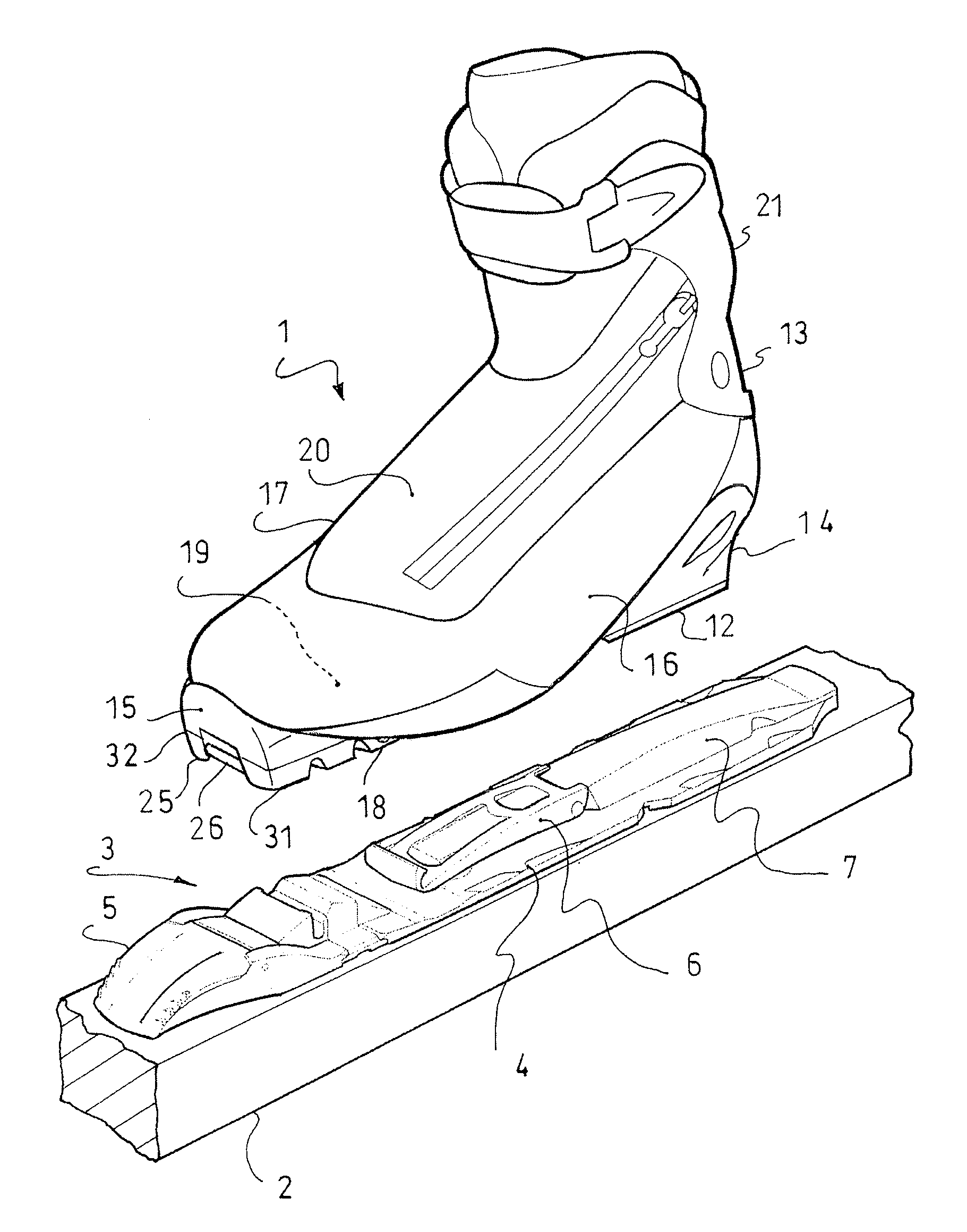
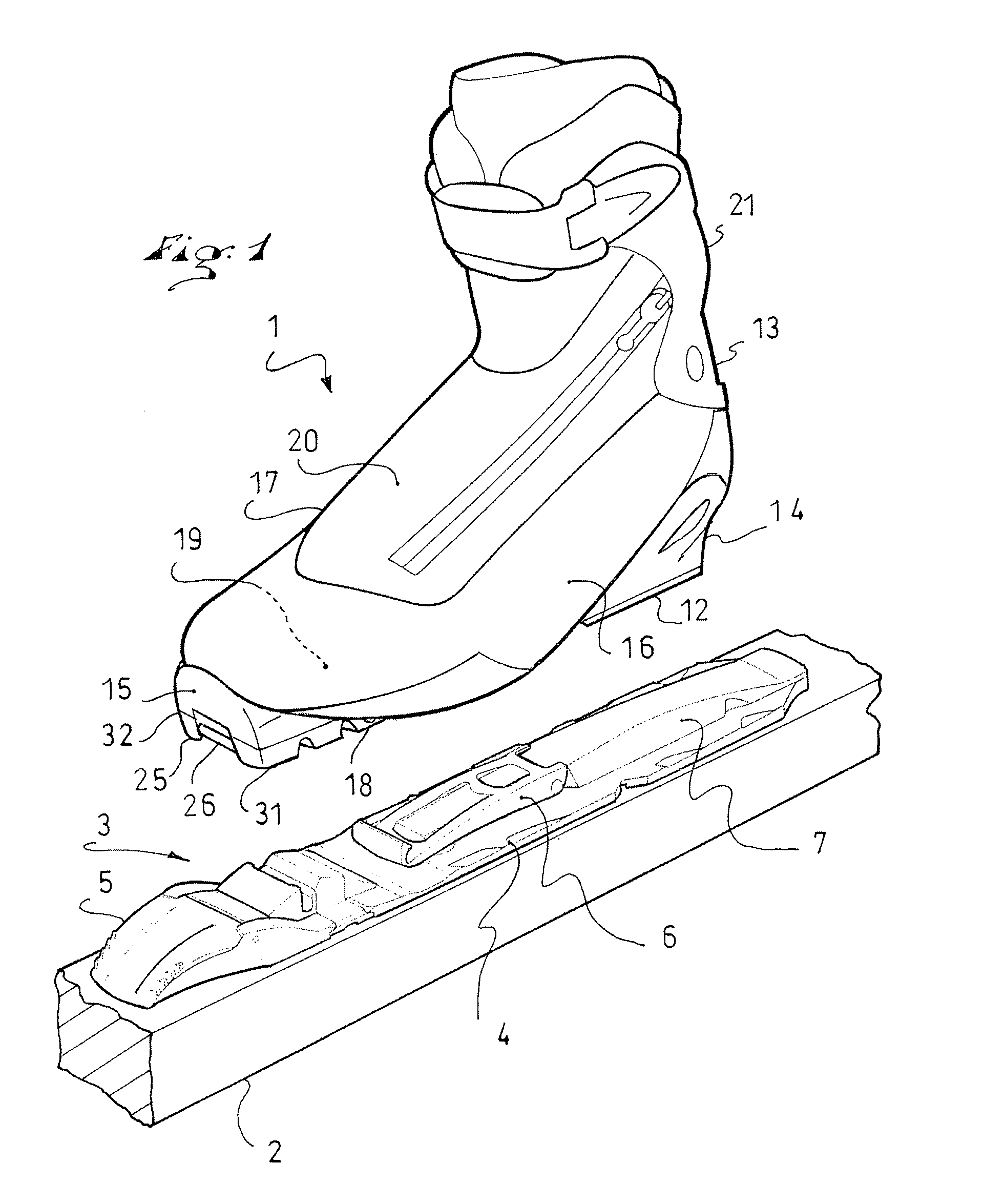
[0038]The first embodiment is illustrated with reference to FIGS. 1 to 4. FIG. 1 shows an assembly that includes a boot 1, a ski 2, and a device 3 for retaining the boot on the ski.

[0039]Conventionally, the retaining device 3 includes a baseplate 4, which carries a reversible locking mechanism 5, an elastic return mechanism 6, and a longitudinal guiding rib 7. For example, it is possible to affix the locking mechanism 5, the return mechanism 6, and the guiding rib 7 to the baseplate 4, to make the retaining device 3 cohesive. The retaining device 3 and the ski 2 will not be further described, as they are well known to one of ordinary skill in the art. The retaining device can be any of various types, such as that disclosed in U.S. Pat. No. 6,017,050, the disclosure of which is hereby incorporated by reference thereto in its entirety.

[0040]The boot 1 includes an outer sole assembly 12 and an upper 13. The outer sole assembly 12 can include one, two, or more portions. The boot 1 exten...

second embodiment

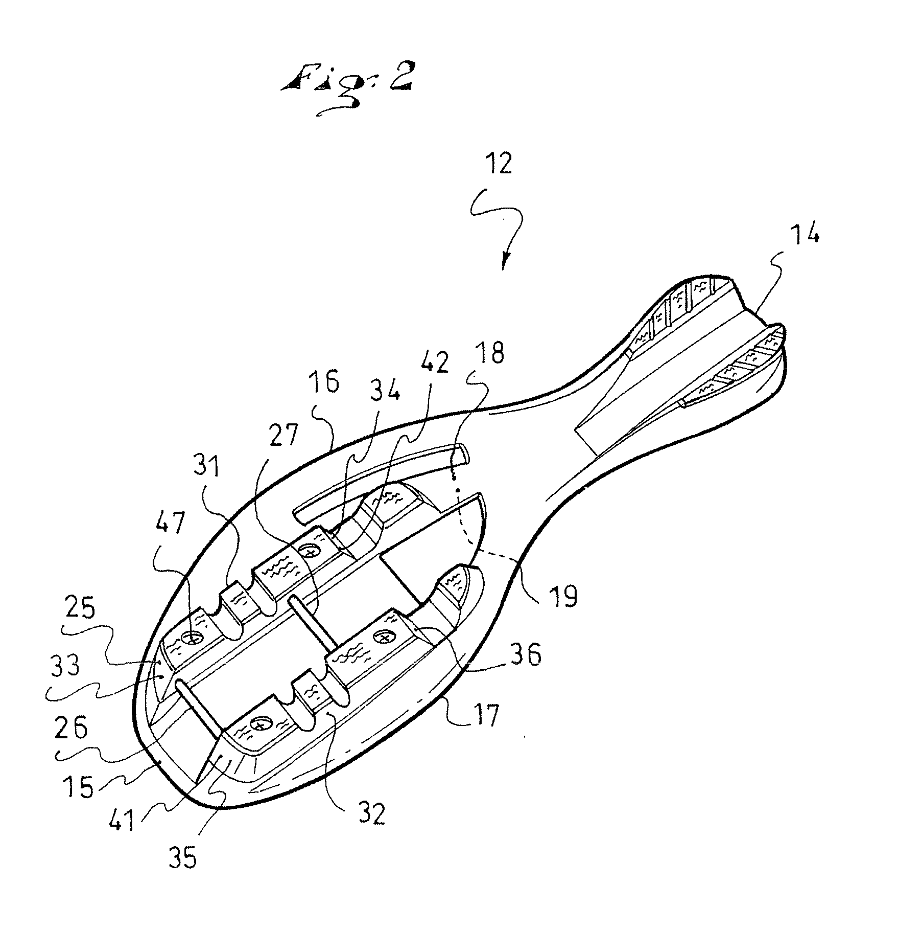
[0060]In this regard, a second embodiment, according to FIGS. 5 to 7, has an outer sole assembly 12, with its rear end 14 and front end 15, its lateral side 16 and medial 17 sides, and its free 18 and connection 19 surfaces. There is also a fastening element 25, with its first 26 and second 27 wires, as well as its first 31 and second 32 longitudinal bars.

[0061]The second embodiment is specific to the manner in which the fastening element 25 is positioned on the outer sole assembly 12. The boot 1 in this case includes a mechanism for positioning the fastening element 25 on the outer sole assembly 12, via a discrete adjustment in at least two positions, viz., a first position for which a first end 41 of the fastening element 25 is located at a first distance from the front end 15 of the boot, and a second position for which the first end 41 of the fastening element 25 is located at a second distance from the front end 15 of the boot. This configuration allows the fastening element 25...

third embodiment

[0065]the invention is illustrated with reference to FIGS. 8 to 13. This embodiment also has an outer sole assembly 12, with its rear 14 and front 15 ends, its lateral 16 and medial 17 sides, and its free 18 and connection 19 surfaces. There is also a fastening element 25, with its first 26 and second 27 wires, as well as its first 31 and second 32 longitudinal bars.

[0066]The third embodiment is also specific to the manner in which the fastening element 25 is positioned on the outer sole assembly 12. The boot 1 in this case includes a mechanism for positioning the fastening element 25 on the outer sole assembly 12, via a continuous adjustment over a nominal range, the displacement of the fastening element 25 relative to the outer sole assembly 12 occurring longitudinally. This arrangement increases the possibilities of adjustment of the position of the fastening element 25. The adjustment is selectively carried out to move the fastening element toward or, conversely, away from the f...


PUM


Abstract

An article of footwear, such as a boot, adapted to be removably retained on a sports apparatus, the boot including an outer sole assembly, an upper and a fastening element, the latter being adapted to cooperate with a locking mechanism, itself adapted to be affixed to the apparatus. The boot includes a connection mechanism adjustable in position, which adjustably connects the fastening element to the outer sole assembly.

Description

CROSS-REFERENCE TO RELATED APPLICATION[0001]This application is based upon French Patent Application No. 10 / 04892, filed Dec. 15, 2010, the disclosure of which is hereby incorporated by reference thereto in its entirety, and the priority of which is claimed under 35 U.S.C. §119.BACKGROUND[0002]1. Field of the Invention[0003]The invention relates to an article of footwear, such as a shoe or a boot, adapted to be reversibly retained on a sports apparatus and, more particularly, such an article of footwear being adapted for the practice of snow sports.[0004]Footwear of the aforementioned type can be used in disciplines such as cross-country or telemark skiing, snowshoeing, roller skating, cycling, and the like.[0005]2. Background Information[0006]An article of footwear (hereafter “boot,” for convenience) of the aforementioned type includes an outer sole assembly, an upper, and a fastening element, the latter being adapted to cooperate with a locking mechanism, which itself is adapted t...

Claims


Application Information

Patent Timeline
IPC IPC(8): A43B5/04
CPCA43B5/0413A43B5/0496A43B5/0494
Inventor MIETTE, PHILIPPE
Owner SALOMON SA
Why Eureka
Try Eureka