Cutter device for cutting mailpieces open

a cutter device and mailpiece technology, applied in the field of mail handling, can solve the problems of generating paper shreds or “chaff" on the device, and not being able to solve the problem of destroying the paper

Active Publication Date: 2012-06-21
NEOPOST TECH SA
View PDF11 Cites 4 Cited by
  • Summary
  • Abstract
  • Description
  • Claims
  • Application Information

AI Technical Summary

Benefits of technology

[0004]An object of the present invention is thus to mitigate those drawbacks with a cutter device for a mail-handling machine that mitigates the above-mentioned drawback by enabling cutting to take place over the entire length(s) of the envelopes in a direction that is exactly parallel to the conveyor surface. Another object of the invention is to enable the cutting to take place over a single face of the envelope so as not to generate chaff. Another object of the invention is to propose a cutter device that is not dependent on cutter manufacturing tolerance.
[0006]Thus, the inclination of the rotary bearing element makes it possible, by jogging the envelope against the conveyor path, to keep it in a constant position while it is moving, and thus to generate cutting that is regular.

Problems solved by technology

Unfortunately, that device is not without drawbacks.
Firstly, that arrangement of the cutters inevitably gives rise to the envelope being cut through completely and thus generates shreds of paper or “chaff” from the cut-off portion of the envelope.

Method used


Image

  • Cutter device for cutting mailpieces open
  • Cutter device for cutting mailpieces open
  • Cutter device for cutting mailpieces open

Examples


Embodiment Construction

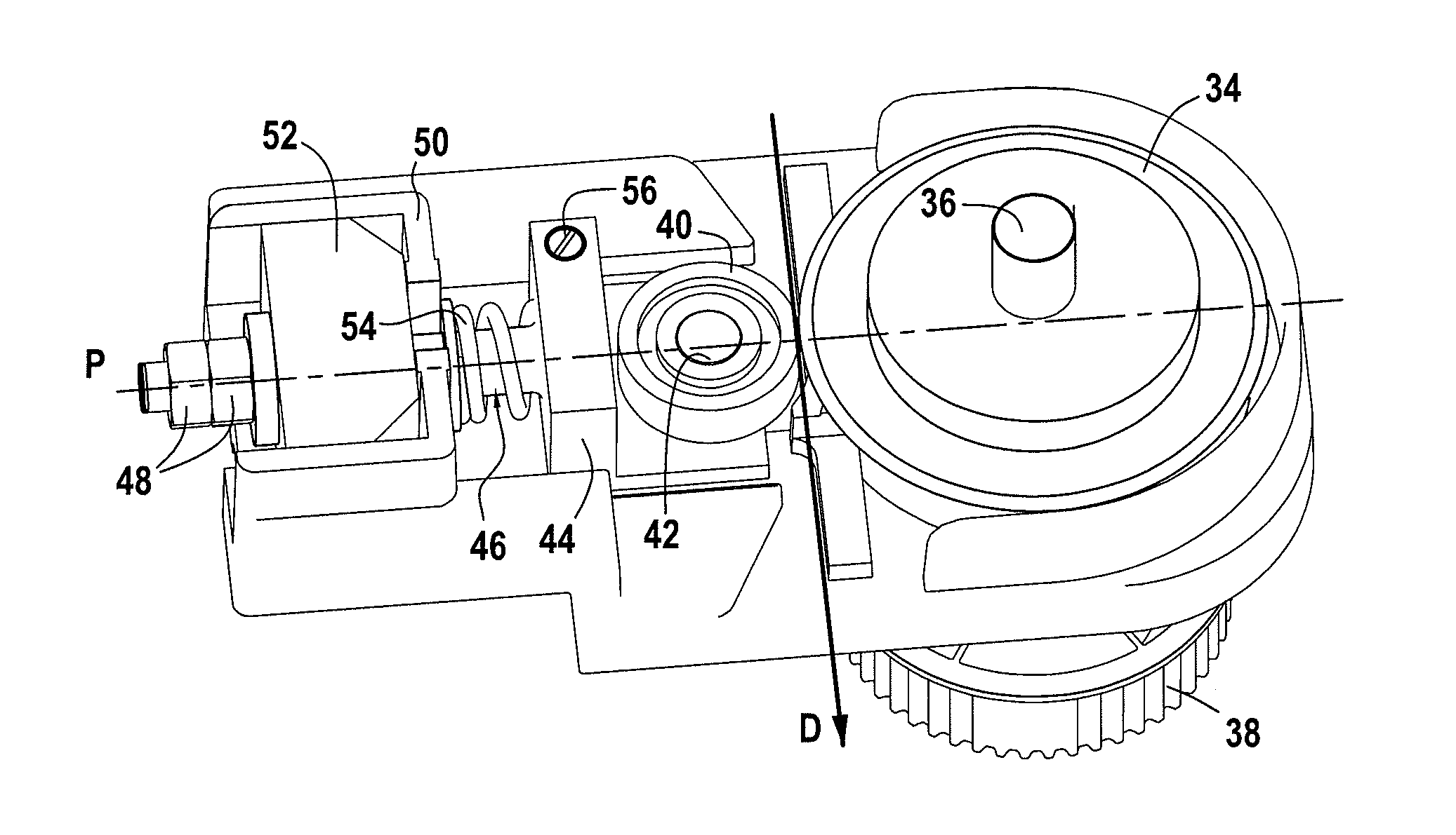
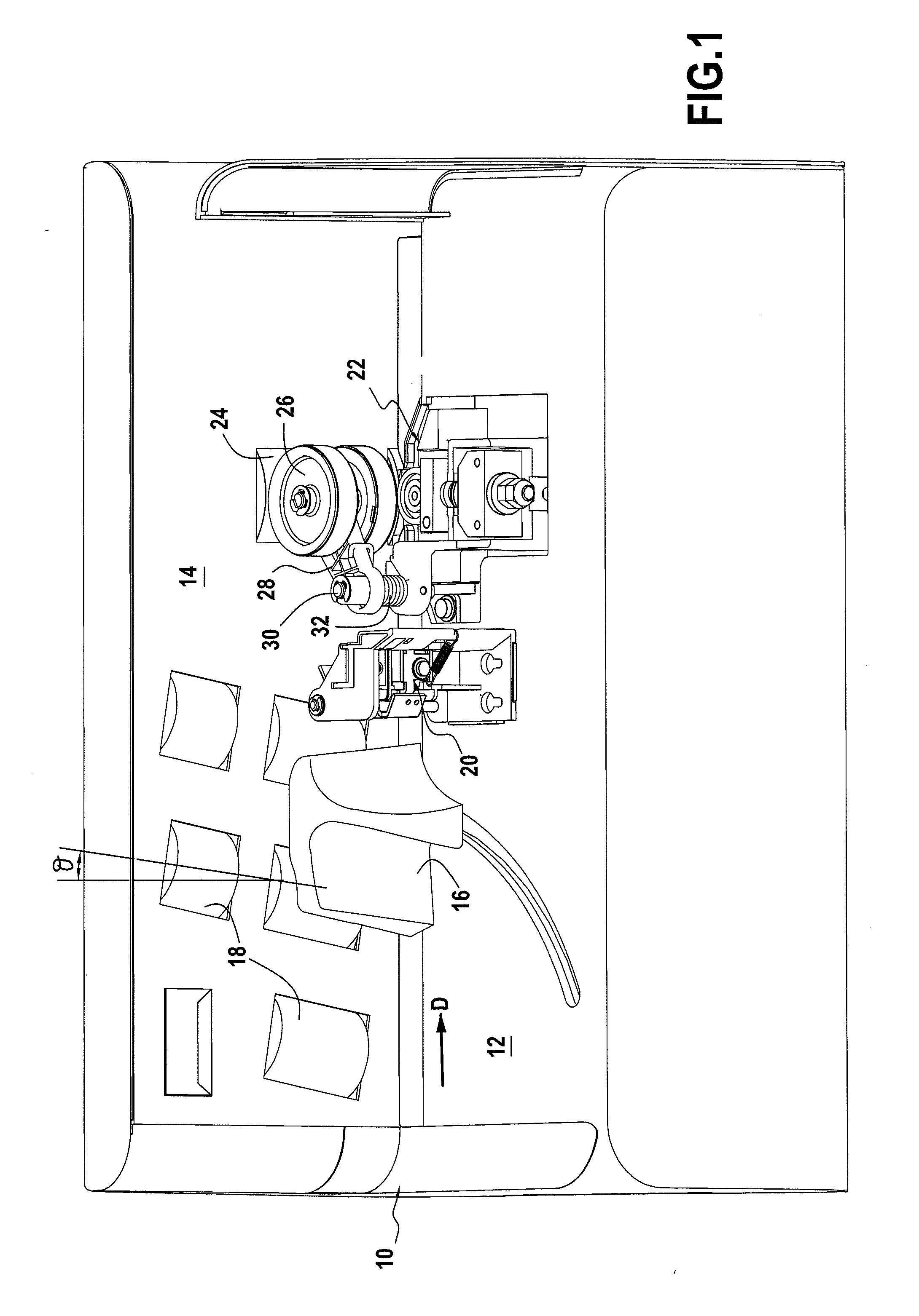
[0020]FIG. 1 shows an example of an envelope-opener machine architecture 10 in which the envelopes to be opened are placed on edge in a stack, preferably formed by a homogeneous batch, resting on an envelope-receiving deck 12. These envelopes are jogged against a vertical conveyor wall 14 by a moving guide 16 pressed against said envelopes, e.g. by spring means (not shown) disposed under the envelope-receiving deck. First motor-driven conveyor rollers 18 stand proud through the vertical conveyor wall for the purpose of moving said envelopes along a conveyor path in a conveying direction D towards a selector device 20 for selecting said envelopes one-by-one, and then towards the cutter device 22 proper. These first conveyor rollers 18 are advantageously inclined towards the envelope-receiving deck at an angle θ lying in the range 5° to 15°.

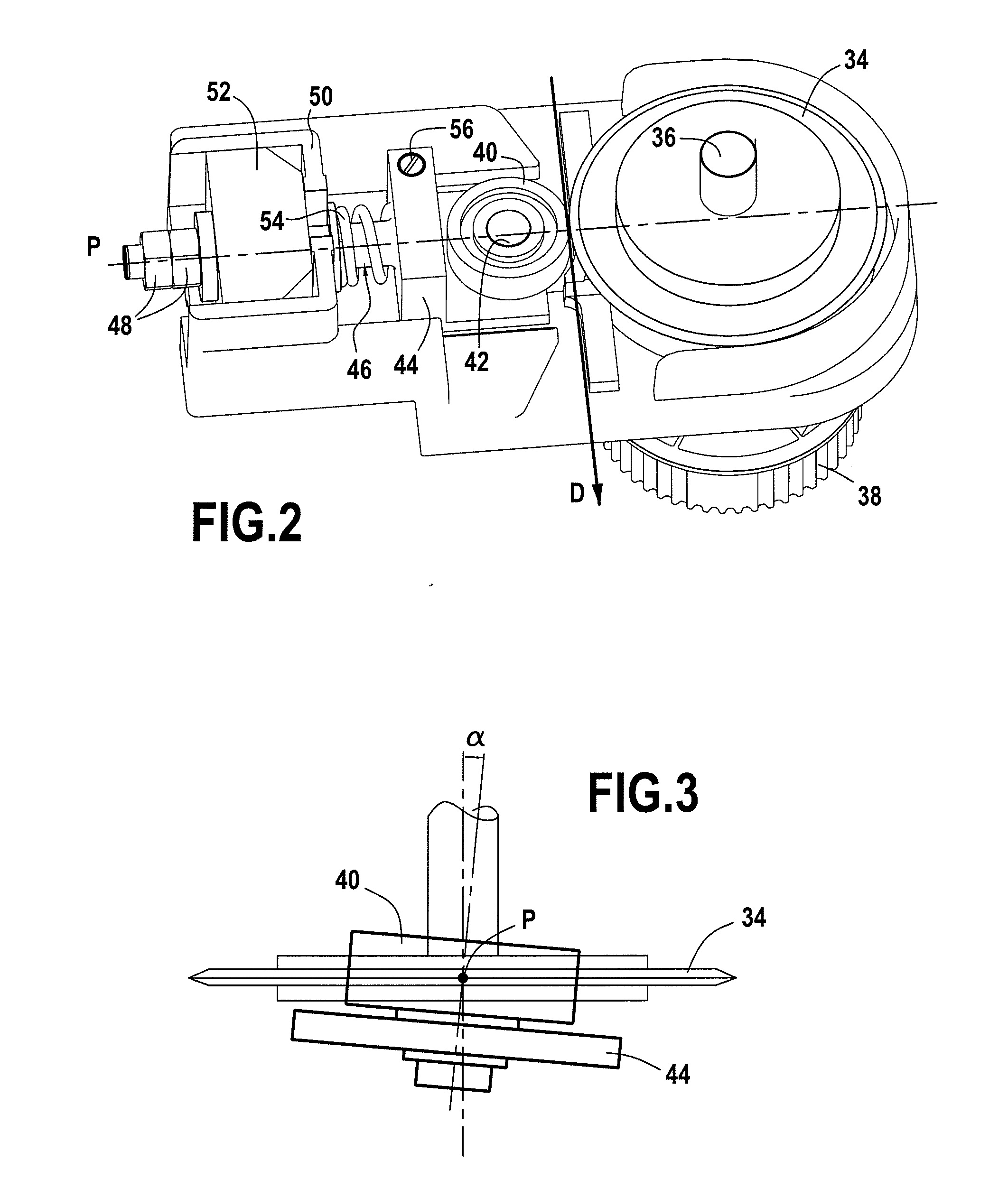
[0021]Second motor-driven conveyor rollers 24 standing proud through the conveyor wall in register with the cutter device are provided for the pur...


PUM

PropertyMeasurementUnit
angle of inclinationaaaaaaaaaa
angleaaaaaaaaaa
thicknessaaaaaaaaaa

Abstract

A cutter device for cutting envelopes open, which cutter device includes a rotary cutter suitable for cutting open an envelope, and a rotary bearing element against which said envelope is in contact as it goes past the rotary cutter, an axis of rotation of the bearing element forming a predetermined angle of inclination with a drive axis of the rotary cutter.

Description

TECHNICAL FIELD[0001]The invention relates to the field of mail-handling and it relates more particularly to a machine for opening envelopes (or “letter opener”) including an improved cutter device.PRIOR ART[0002]U.S. Pat. No. 5,156,515 discloses a mechanical letter opener in which the cutter device is made up of two cutting members, namely a top member and a bottom member, which may be referred to as “cutter wheels” or as “cutters” and which are disposed in offset manner in the cutting plane so that their adjacent inclined edge faces can appropriately flank the envelope to be cut open.[0003]Unfortunately, that device is not without drawbacks. Firstly, that arrangement of the cutters inevitably gives rise to the envelope being cut through completely and thus generates shreds of paper or “chaff” from the cut-off portion of the envelope. Secondly, depending on the mode of conveying used for moving the envelopes, if the diameter(s) of the drive rollers in contact with the envelope whil...

Claims


Application Information

Patent Timeline
Patent Type & Authority Applications(United States)
IPC IPC(8): B26D1/22B26D3/12B65H5/00
CPCB43M7/00Y10T83/6604Y10T83/741Y10T83/7813
Inventor BENARD, SERGEBERNARD, DOMINIQUE
Owner NEOPOST TECH SA
Why Eureka
Try Eureka