Electronic control system for a tubular handling tool

Active Publication Date: 2012-06-21
WEATHERFORD TECH HLDG LLC
View PDF3 Cites 95 Cited by
  • Summary
  • Abstract
  • Description
  • Claims
  • Application Information

AI Technical Summary

Benefits of technology

[0010]In one embodiment, a method of controlling a tubular handling tool comprises measuring an operational characteristic of the tubular handling tool; communicating the operational characteristic to a controller in the form of an electronic signal; and using the controller to control actuation of the tubular handling tool in response to the measured operational characteristic. The method further comprises sending an electronic signal to a valve to actuate the valve and thereby supply or release fluid pressure to the tubular handling tool. The method further comprises actuating the tubular handling tool by actuating an electronically controlled valve with the controller.
[0011]In one embodiment, a tubular handling system comprises a tubular handling tool having a sensor configured to measure an operational characteristic of the tubular handling tool; an electronic control system in communication with the sensor; and a rig winch system in communication with the electronic control system, wherein the rig winch system is operable to raise or lower the tubular handing tool in response to the operational characteristic measured by the sensor and communicated to the electronic control system.
[0012]In one embodiment, a tubular handling system comprises an actuation assembly; a gripping tool coupled to the actuation assembly such that the actuation assembly is operable to actuate the gripping tool; a first sensor coupled to the actuation assembly; and an identification device. The first sensor is operable to communicate with the identification device and transmit a signal to an electronic control system corr

Problems solved by technology

At any given time, the operator can inadvertently

Method used


Image

  • Electronic control system for a tubular handling tool
  • Electronic control system for a tubular handling tool
  • Electronic control system for a tubular handling tool

Examples


Embodiment Construction

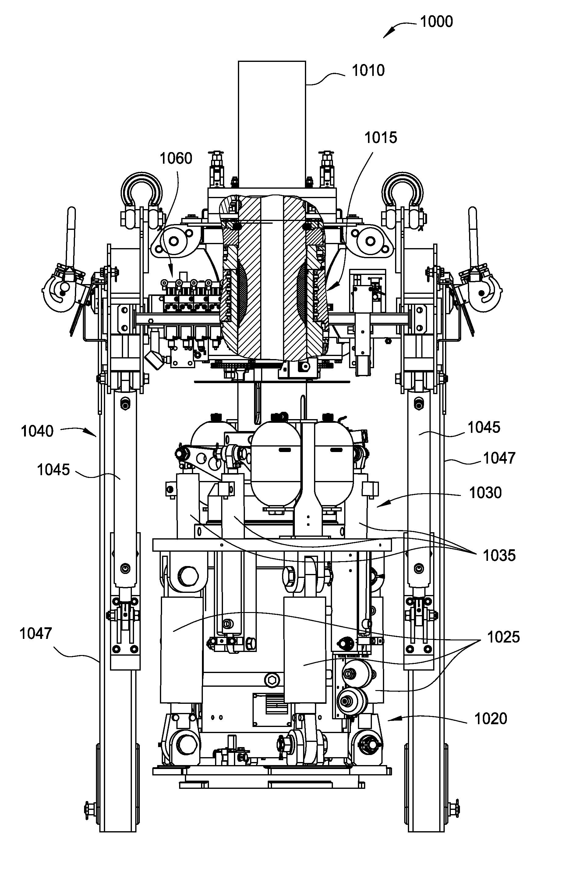
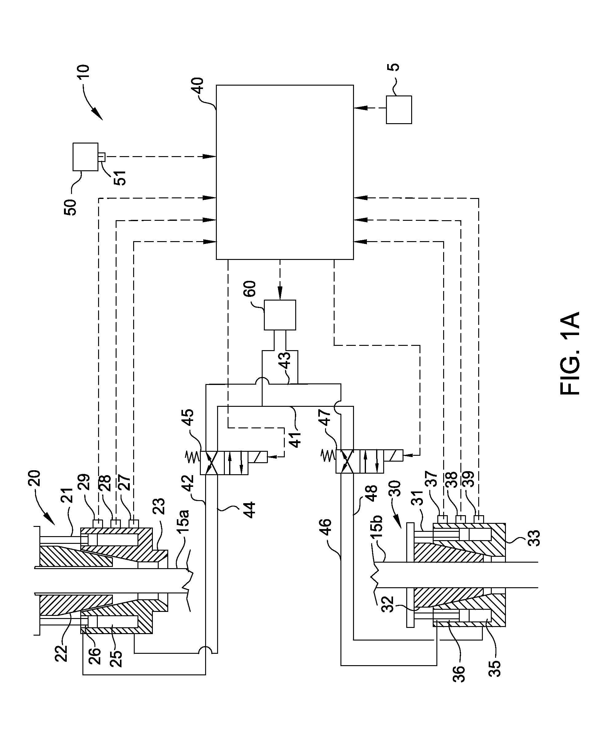
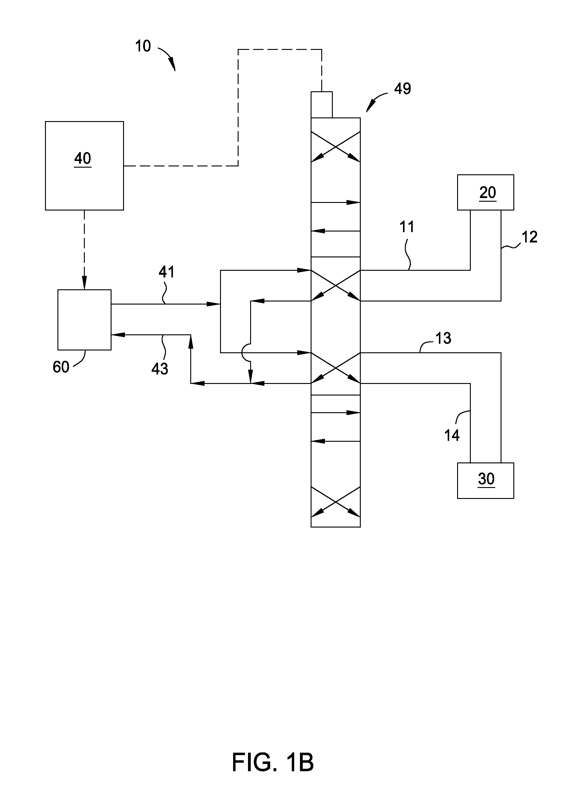
[0027]FIG. 1A illustrates an electronic control system 10 for controlling the operation of a first tubular handling tool 20, such as an elevator or other similar tubular gripping device, and / or a second tubular handling tool 30, such as a spider, to prevent the inadvertent release of one or more tubulars 15a, 15b. The first and second tubular handling tools 20, 30 may each include at least one piston / cylinder assembly 21, 31, gripping assembly 22, 32, and housing assembly 23, 33 for gripping and supporting tubulars 15a, 15b. Pressurization of the piston / cylinder assemblies 21, 31 moves the gripping assembly 22, 32 radially inwardly and outwardly to engage and disengage the tubulars 15a, 15b. A top drive system may be used to rotate the first tubular handling tool 20, to thereby rotate tubular 15a and make up or break out a connection with tubular 15b, which is supported by the second tubular handling tool 30. In one embodiment, the first tubular handling tool 20 may be an elevator w...


PUM


Abstract

An electronic control system comprises a first tubular handling tool, a sensor, and a controller. The controller is configured to control actuation of the first tubular handling tool in response to an electronic signal received from the sensor that corresponds to an operational characteristic of the first tubular handling tool. The electronic control system functions as an electronic interlock system to prevent mishandling of a tubular. A method of controlling a tubular handling tool comprises measuring an operational characteristic of the tubular handling tool, communicating the operational characteristic to a controller in the form of an electronic signal, and using the controller to control actuation of the tubular handling tool in response to the measured operational characteristic.

Description

CROSS-REFERENCE TO RELATED APPLICATIONS[0001]This application claims the benefit of U.S. Provisional Application No. 61 / 424,575, filed Dec. 17, 2010, and U.S. Provisional Application No. 61 / 516,609, filed Apr. 5, 2011, each application of which is herein incorporated by reference in its entirety.BACKGROUND OF THE INVENTION[0002]1. Field of the Invention[0003]Embodiments of the invention relate to an electronic control system for controlling the operation of one or more tubular handling tools. Embodiments of the invention relate to an electronic interlock for a tubular handling system for performing tubular handling operations.[0004]2. Description of the Related Art[0005]It is known in the drilling industry to use a top drive system on a drilling rig for rotating a tubular or tubular string for making up or breaking out tubular connections while drilling a well and for installing the casing after the well is drilled. Top drive systems are equipped with a motor to provide torque for r...

Claims


Application Information

Patent Timeline
IPC IPC(8): E21B19/16E21B47/00E21B19/10E21B19/07
CPCE21B19/07E21B47/00E21B19/16E21B19/10E21B19/06E21B19/165E21B19/00
Inventor WIEDECKE, MICHAELTHIEMANN, BJOERNHEIDECKE, KARSTENLIESS, MARTINHELMS, MARTINHOOKER, II, JOHN D.
Owner WEATHERFORD TECH HLDG LLC
Why Eureka
Try Eureka