
Sterilization Container With Releasable and Permanent Lock

a technology of sterilization container and lock, which is applied in the direction of pliable tubular container, liquid handling, caps, etc., can solve the problems of contamination to reach the items, and other sources of small tears or snags in the barrier,

Active Publication Date: 2012-06-21
O&M HALYARD INC
View PDF10 Cites 15 Cited by
  • Summary
  • Abstract
  • Description
  • Claims
  • Application Information

AI Technical Summary

Benefits of technology

[0002]Sterilization wrap is used by enveloping the medical equipment with the wrap, which is generally made of a gas permeable material like a non-woven fabric. Examples of such wraps may be found in U.S. Pat. No. 6,406,674, which describes a wrap of two layers bonded in such a way as to remain visibly two layers to a casual viewer. This wrap is superior to single layer wraps as it provides greater resistance to wear and tear.
[0003]Regarding sterilization wraps; sterilization wraps are made of a relatively thin, flexible material and have low initial cost and are typically disposable, i.e., discarded after a single use. Items to be sterilized are usually placed within a metal sterilization tray prior to wrapping the items with sterilization wrap. These sterilization trays have pointed edges or other features that may concentrate forces and generate very small tears or snags if the wrap contacts them. When wrapped trays are transported on carts or stacked prior to sterilization or after sterilization, other sources of very small tears or breaches in the barrier may develop in the wrap due to pressure or impact. These tears may allow contaminates to reach the items. The result is added expense because the items need to re-handled, re-wrapped and re-sterilized.
[0019]The locking elements may be arranged along the outer edge of the lid and tray and may be between a centimeter in length, to quite large, e.g. 10 cm or more. In the case of a large sterilization container, multiple large locks may deployed along each side to help to ensure that the barrier between the lid and tray does not become ruptured or damaged and allow the passage of microorganisms into the container.

Problems solved by technology

These sterilization trays have pointed edges or other features that may concentrate forces and generate very small tears or snags if the wrap contacts them.
When wrapped trays are transported on carts or stacked prior to sterilization or after sterilization, other sources of very small tears or breaches in the barrier may develop in the wrap due to pressure or impact.
These tears may allow contaminates to reach the items.
The result is added expense because the items need to re-handled, re-wrapped and re-sterilized.
In addition, because sterilization wraps are not transparent, the medical professional cannot visually inspect the items within the wrap for content or for assurance that the sterilization procedure has been completed.
This can lead to a medical professional opening the wrong sterilization tray during a procedure and / or lead to lack of confidence that the tray is truly sterilized.
As a result, trays and articles may require unnecessary re-handling and re-sterilization, wasting time and money.
Reusable vented rigid sterilization containers, although generally effective, are locked closed prior to sterilization and cannot be reopened once locked except through the breaking of the lock.
This is inefficient and wasteful.
Although utilization of sterilization wrap and / or use of vented rigid reusable sterilization containers are generally effective, there are certain disadvantages associated with each of these techniques.
As noted above, wraps may suffer from difficult to find cuts and tears that may render them ineffective and which may provide a pathway for microorganisms to re-enter the instrument basket after sterilization.
Rigid vented sterilization containers are generally not transparent and are locked shut once the instruments are placed inside, making visual inspection and instrument content checking impossible without breaking open the container and repacking and re-sterilizing it.

Method used


Image

  • Sterilization Container With Releasable and Permanent Lock
  • Sterilization Container With Releasable and Permanent Lock
  • Sterilization Container With Releasable and Permanent Lock

Examples


Embodiment Construction

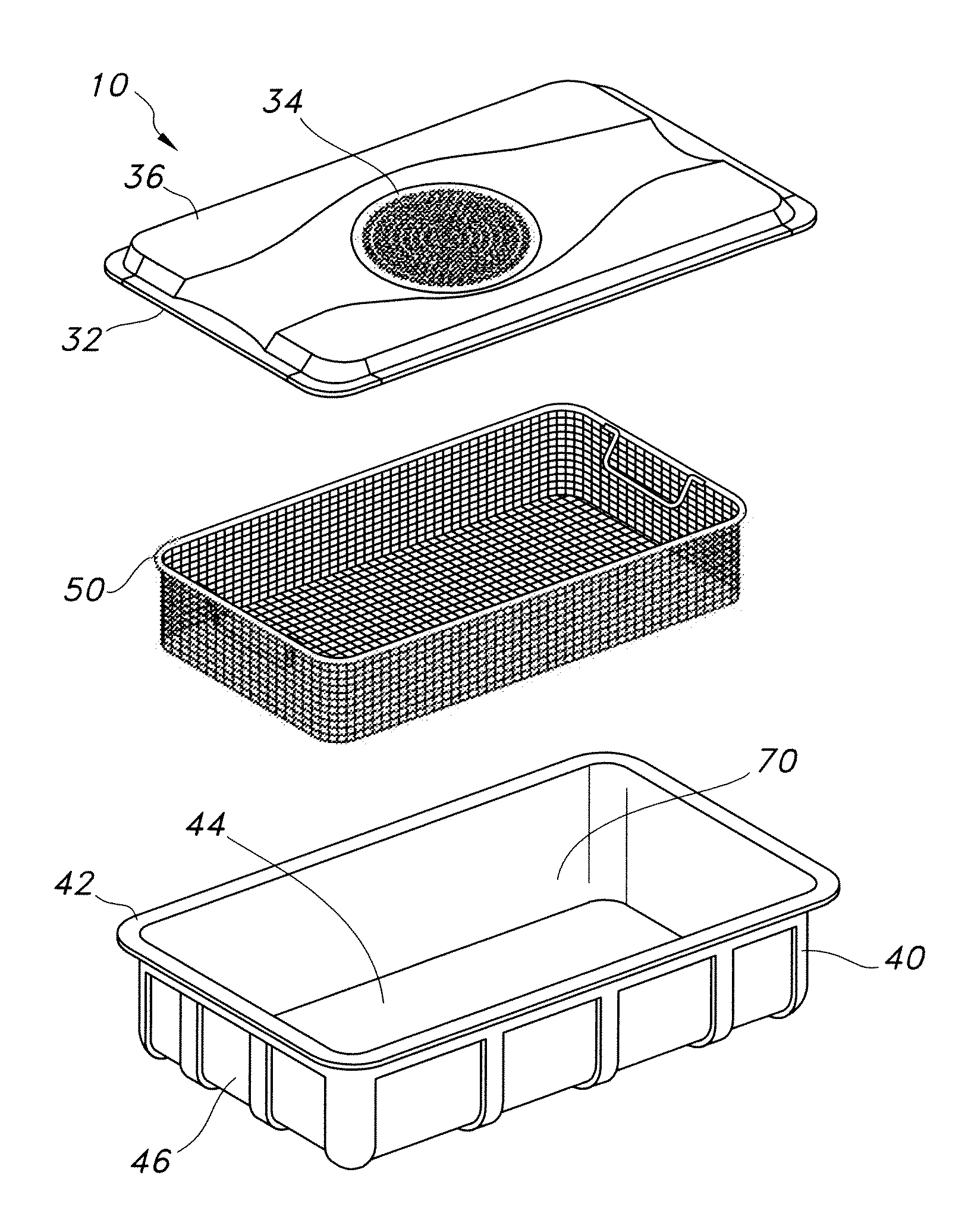
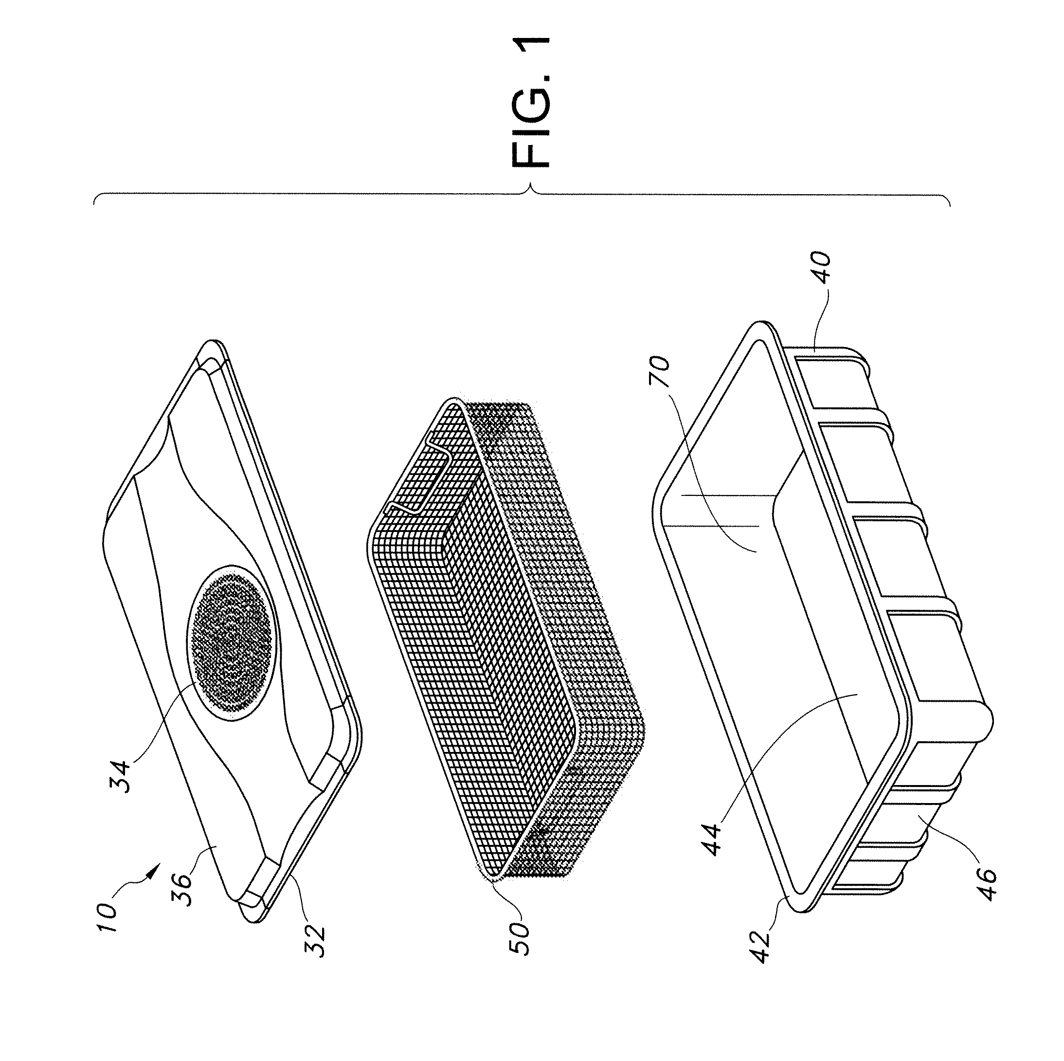
[0027]The present disclosure provides a locking container for sterilizing and storing surgical materials and aseptically opening and aseptically preserving surgical materials in a sterilized condition. These containers offer an increased level of confidence of the sterility of the contents while allowing a user to open the container prior to sterilization to check the contents to ensure that the proper instruments are present in the container. This functionality also allows a user to add an item that may be needed for a specialized surgery or to subtract an extra item that is not needed for a particular surgery.

[0028]The disclosure will be described with reference to the following description and figures which illustrate certain embodiments. It will be apparent to those skilled in the art that these embodiments do not represent the full scope of the disclosure which is broadly applicable in the form of variations and equivalents as may be embraced by the claims appended hereto. Furt...


PUM

PropertyMeasurementUnit
Melting pointaaaaaaaaaa
Water vapor transmission rateaaaaaaaaaa
Permeabilityaaaaaaaaaa

Abstract

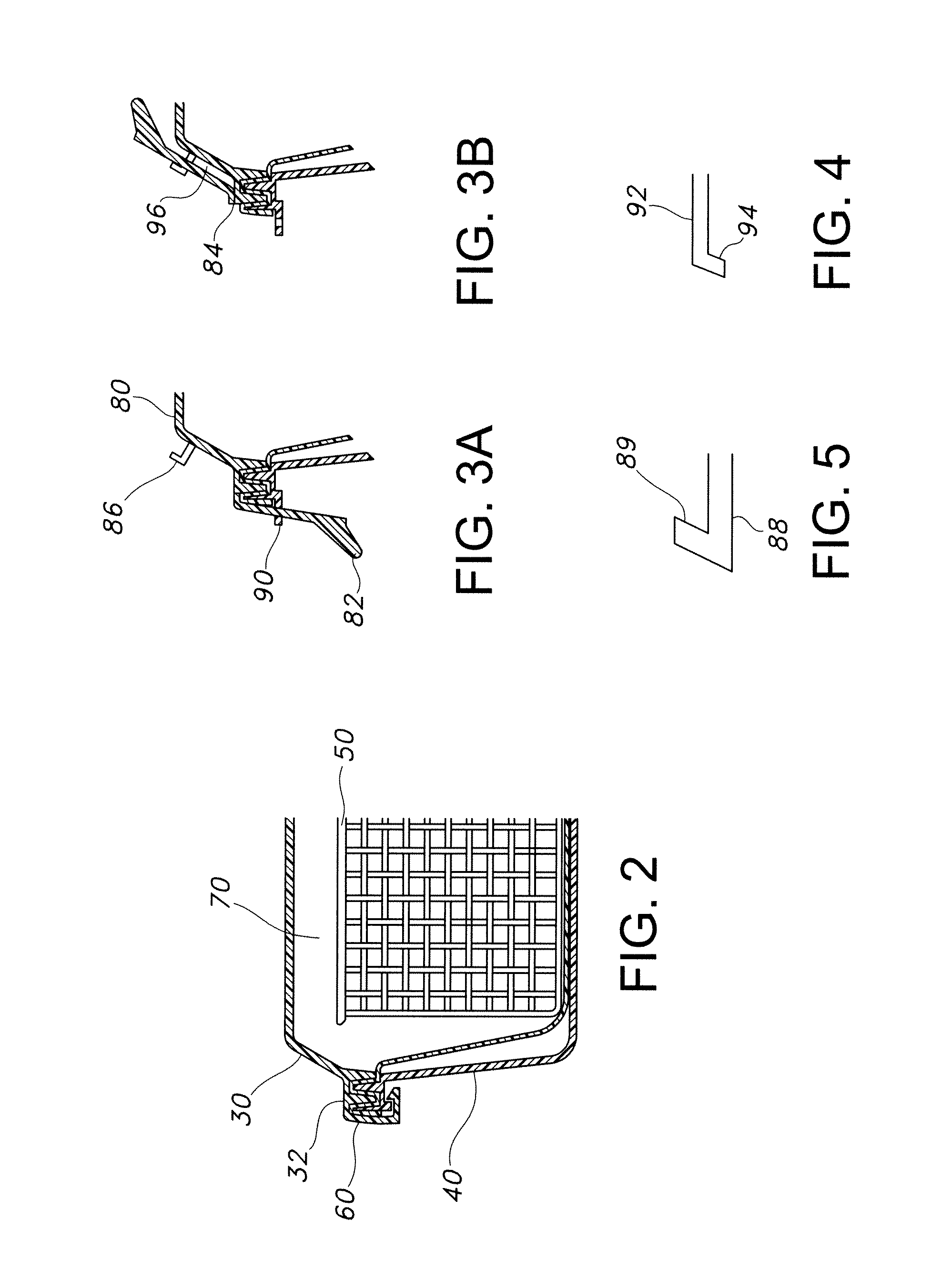
A container for sterilizing and storing surgical materials and preserving surgical materials in a sterilized condition is provided. The container can include a lid and tray that may be used to contain an instrument basket for sterilization. The container has a lock that releasably holds the lid and tray together and that can rotate into a second position, after it is released, and non-releasably lock into the second position.

Description

[0001]Medical equipment is sterilized prior to surgical use in order to avoid harmful and infectious microbes being introduced to patients. There are two generally available methods of performing sterilization of medical equipment. One of the methods involves the use of a “sterilization wrap” fabric and the other uses a sterilization container into which the instruments are placed.[0002]Sterilization wrap is used by enveloping the medical equipment with the wrap, which is generally made of a gas permeable material like a non-woven fabric. Examples of such wraps may be found in U.S. Pat. No. 6,406,674, which describes a wrap of two layers bonded in such a way as to remain visibly two layers to a casual viewer. This wrap is superior to single layer wraps as it provides greater resistance to wear and tear.[0003]Regarding sterilization wraps; sterilization wraps are made of a relatively thin, flexible material and have low initial cost and are typically disposable, i.e., discarded after...

Claims


Application Information

Patent Timeline
IPC IPC(8): B65D25/14B65D55/14B65D45/00E05B65/00
CPCA61L2/26A61L2202/182A61L2202/24B65D43/0216B65D2543/00564B65D2255/20B65D2543/0012B65D2543/00296B65D2543/00435B65D55/02Y10T70/50Y10T70/5549Y10T292/444
Inventor SMITH, TARA DENISE
Owner O&M HALYARD INC
Learn More