Method for presenting spatial attitude and heading information of a vehicle

a technology of heading information and attitude, applied in the field of flight guidance equipment, can solve the problems of not being able to easily know in which direction he should steer to get a normal flight attitude, not being able to provide instantaneous situation awareness, and not being able to provide actual attitude or directions to correct attitude, etc., to achieve the effect of improving awareness situation and improving safety

Inactive Publication Date: 2012-06-21
AIRBUS HELICOPTERS DEUT GMBH
View PDF7 Cites 7 Cited by
  • Summary
  • Abstract
  • Description
  • Claims
  • Application Information

AI Technical Summary

Benefits of technology

[0060]An advantage of the method according to the invention lies in the direct spatial presentation of the vehicle's attitude while the crew member is still steering the inside-out part of the indication. It is a more intuitive presentation and supports the spatial orientation gathering especially in case of distraction or high workload, as the crew member will be in a third party observer position, which supports getting back the necessary overview for an abnormal situation.
[0061]An advantage of the artificial spatial attitude indicator conforming to the invention, resides in that it provides the pilot with reliable attitude information which do not require too ma

Problems solved by technology

The current state of the art equipments, however, cannot provide such instantaneous situation awareness.
It can occur that the pilot can see only the earth or only a blue sky in his primary flight display of the known equipments and that he cannot easily know in which direction he should steer to get a normal level of flight attitude.
Those modes are lacking any information about the actual attitude or directions to correct the attitude.
The attitude indication provided by an inside-out view on a known artificial horizon has led to some abnormal situations and was so not considered as satisfactory.
In high workload situations, such markings can easily be neglected by the crew as they might be occupied by other distraction coming from the aircraft or from the environment.
None of the above mentioned known indicators (inside-out or outside-in) are is therefore satisfactory.
In this embodiment, there is a need of the two information elements, the pitch, which renders such a solution relatively complex.
The drawback for this solution is the overlay of two moving elements, one representing the horizon, in order to provide

Method used


Image

  • Method for presenting spatial attitude and heading information of a vehicle
  • Method for presenting spatial attitude and heading information of a vehicle
  • Method for presenting spatial attitude and heading information of a vehicle

Examples


Embodiment Construction

[0072]The identical structural and functional elements, which are shown in several different figures or illustrations, are given one single numeric or alphanumeric reference.

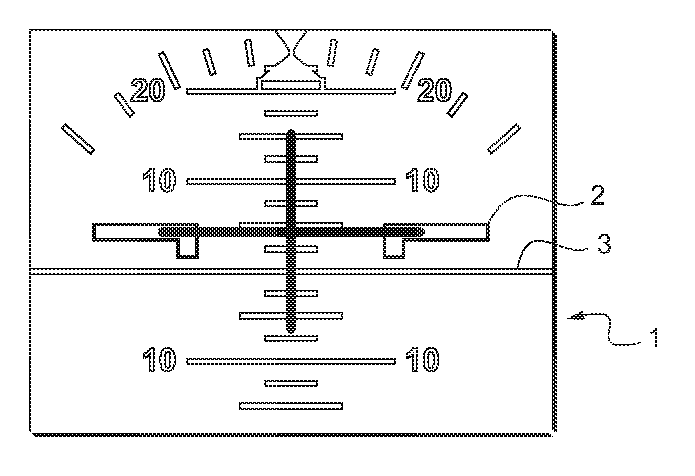
[0073]In FIG. 1, an artificial spatial attitude indicator 1 of the state of the art comprises a fixed aircraft symbol 2 a horizon 3. As depicted in FIG. 1, the available field of view is approximately + / −20°. This leads to a loss of information as soon as the flight attitude is above or below this value. Especially if this situation is combined with a roll motion, a spatial disorientation can easily occur. Additional guidance needs to be introduced to overcome this problem. This would require intensive training for crew to undertake quickly the necessary flight corrections.

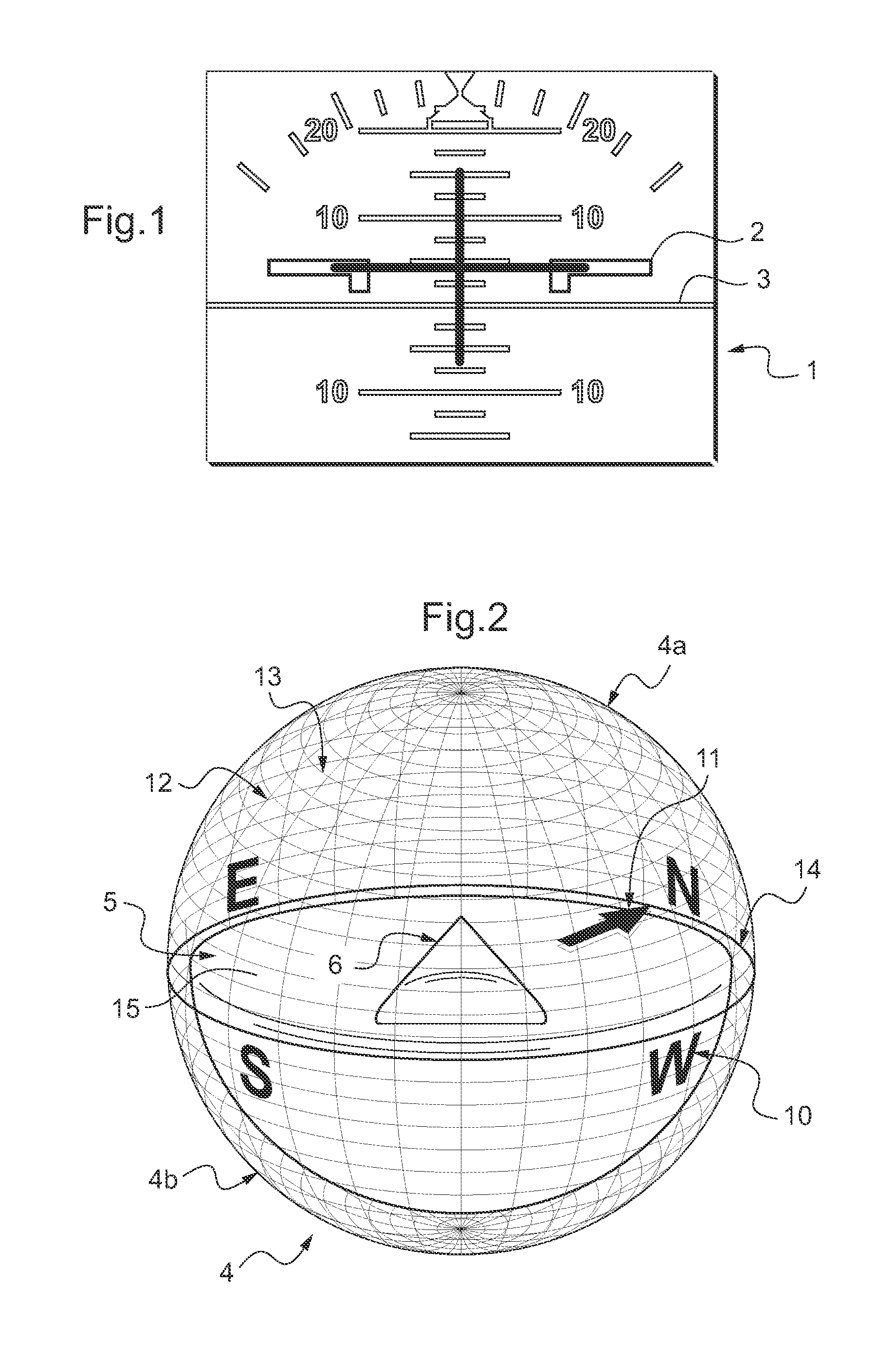
[0074]According to the invention, the artificial spatial attitude and heading indicator for a vehicle such as an aircraft or a spacecraft, comprising a 2D display, an inertial reference system, a computer and a graphical software or a graphic ...


PUM


Abstract

A method of presenting attitude and heading information of a vehicle on a display to a viewer inside the given vehicle, comprising the steps of: using a 2D display, using data provided by an inertial reference system, using a computer and graphical software for treating the data and defining graphical elements, depicting the graphical elements in 3D on the 2D display, and presenting the attitude and heading information on the 2D display by associating them to at least one graphical element.

Description

CROSS REFERENCE TO RELATED APPLICATIONS[0001]This application claims priority to European application no. 10 400064.1 filed Dec. 17, 2010, the disclosure of which is incorporated in its entirety by reference herein.BACKGROUND OF THE INVENTION[0002](1) Field of the Invention[0003]The present invention relates to the general technical field of equipments used for flight guidance.[0004]The invention concerns more particularly a method for presenting attitude and heading information of a vehicle and artificial spatial attitude and heading indicators or instruments of vehicle.[0005](2) Description of Related Art[0006]The term “vehicle” encompasses any type of aircrafts or spacecrafts.[0007]Different terms are used and for which the meaning is given by the definitions as follows:[0008]2D: two dimensional,[0009]3D: three dimensional,[0010]AHRS: attitude and heading reference system,[0011]CDI: Course Deviation Indicator[0012]EFIS: electronic flight information system,[0013]Heading: Directio...

Claims


Application Information

Patent Timeline
IPC IPC(8): G01C21/00
CPCG01C23/00
Inventor SCHMIDT, SVEN
Owner AIRBUS HELICOPTERS DEUT GMBH
Why Eureka
Try Eureka