Interference filter assembly

a filter and assembly technology, applied in the direction of optics, optical elements, instruments, etc., can solve the problem of difficulty in outputing light in the desired wavelength band

Inactive Publication Date: 2012-06-21
DENSO CORP
View PDF5 Cites 34 Cited by
  • Summary
  • Abstract
  • Description
  • Claims
  • Application Information

AI Technical Summary

Benefits of technology

[0008]In a state where the condenser lens and the collimating lens are spaced from each other by the predetermined distance, when a light focused in the condenser lens enters the circular hyperboloid of the collimating lens, a collimated light is generated without being affected by a spherical aberration of the condenser lens. Therefore, it is less likely that rays of light other than the collimated light will enter the interference filter. Accordingly, it is less likely that the function of the interference filter will be seemingly degraded, and hence a function of the interference filter assembly enhances.

Problems solved by technology

However, if the light does not perpendicularly enter the interference filter due to the scatter, it is difficult to output the light in the desired wavelength band.

Method used


Image

  • Interference filter assembly
  • Interference filter assembly
  • Interference filter assembly

Examples


Embodiment Construction

[0012]Hereinafter, an exemplary embodiment will be described with reference to the drawings.

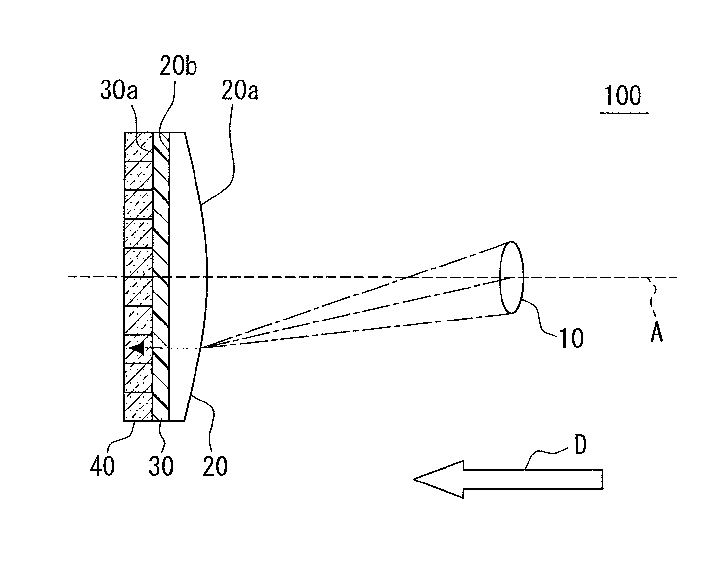
[0013]Referring to FIG. 1, an interference filter assembly 100 is exemplarily employed to apply collimated light in a predetermined wavelength band to an imaging device.

[0014]The interference filter assembly 100 includes a condenser lens 10 for focusing light, a collimating lens 20 for generating collimated light, an interference filter 30 selectively transmitting a light in a predetermined wavelength band, and an imaging device 40.

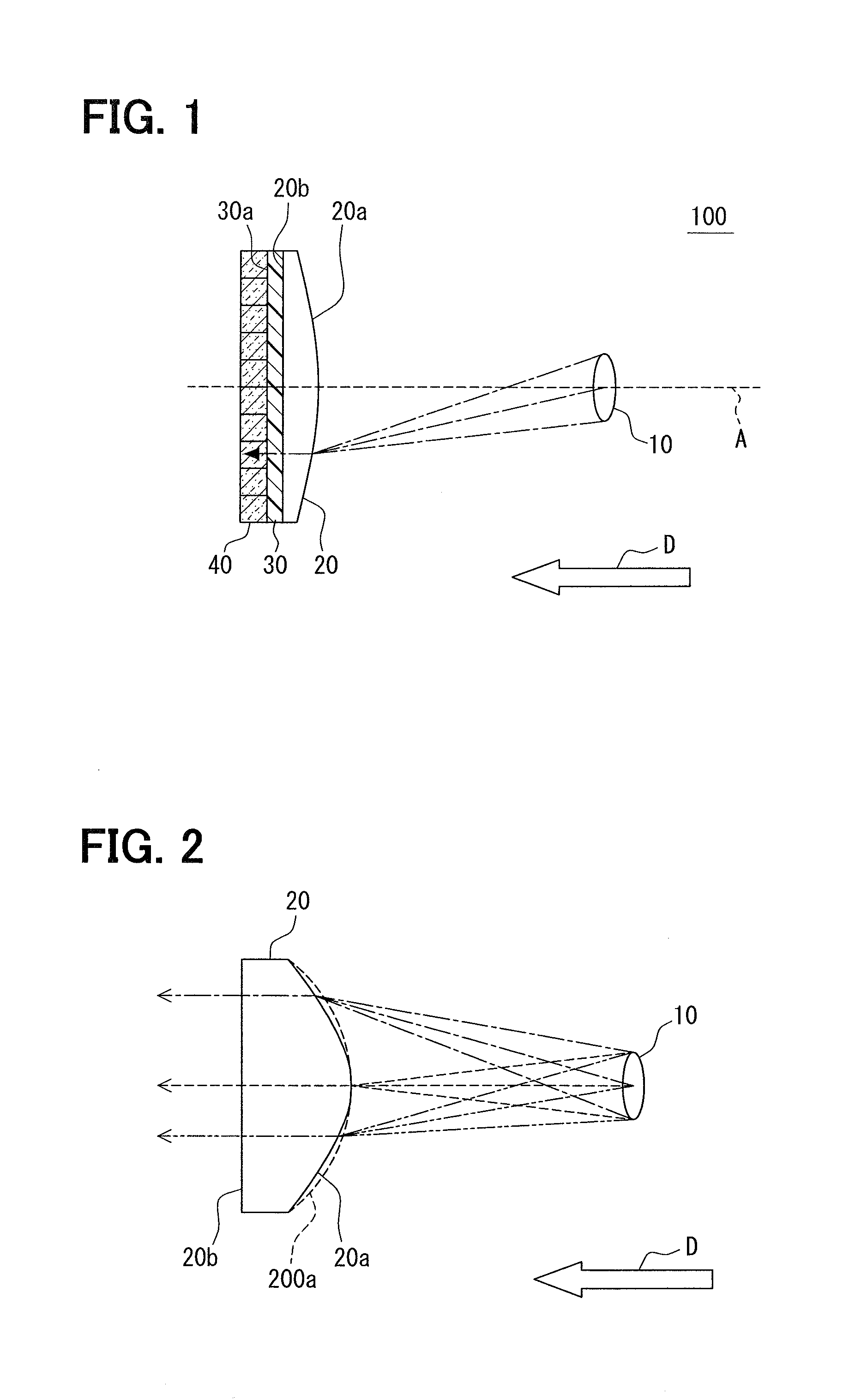
[0015]In FIG. 1, a dotted line A denotes an optical axis. Also, a dashed-line illustrates rays of light entering the imaging device 40 through the condenser lens 10, the collimating lens 20 and the interference filter 30. In FIG. 2, rays of light that enter the collimating lens 20 from the condenser lens 10 are illustrated by a dashed line, a dashed-chain line, and a double dashed-chain line. A surface 20a of the collimating lens 20 is not a spherical surface. In F...


PUM


Abstract

An interference filter assembly includes a condenser lens, a collimating lens, an interference filter, and an imaging device, which are arranged in a direction of light travel. The collimating lens is spaced from the condenser lens by a predetermined distance that corresponds to one of a focal length of the condenser lens and a focal length of the collimating lens. The collimating lens is provided by a single lens and applies a collimated light toward the imaging device through the interference filter in the direction of light travel. The collimating lens has a first surface adjacent to the condenser lens and a second surface adjacent to the interference filter. The first surface is a curved surface that is convex toward the condenser lens and a circular hyperboloid. The second surface is a plane surface and outputs the collimated light to the interference filter.

Description

CROSS REFERENCE TO RELATED APPLICATION[0001]This application is based on Japanese Patent Application No. 2010-280812 filed on Dec. 16, 2010, the disclosure of which is incorporated herein by reference.FIELD OF THE INVENTION[0002]The present invention relates to an interference filter assembly in which a condenser lens, a collimating lens, and an interference filter are arranged in a direction of light travel.BACKGROUND OF THE INVENTION[0003]For example, JP07-49417A describes an interference filter assembly including two microlenses and an interference filter disposed between the two microlenses. One of the microlenses, which is in front of the interference filter, is located at a focal position of a focusing system. The other of the microlenses, which is behind the interference filter, is located at a position to form an image to a detecting element array. The front microlens collimates light focused in the focusing system. The interference filter transmits the collimated light outp...

Claims


Application Information

Patent Timeline
Patent Type & Authority Applications(United States)
IPC IPC(8): G02B5/28
CPCG02B5/28
Inventor MORIGUCHI, CHIHIROANDO, HIROSHIMORIKAWA, KATSUHIRO
Owner DENSO CORP
Why Eureka
Try Eureka