Silent chain

a technology of silent chain and back plate, applied in the direction of driving chain, belt/chain/gearring, chain elements, etc., can solve the problems of easy to tell, simple matter of reliably preventing assembly errors, and production costs of sliding plates, so as to reduce the contact surface area of silent chain, reduce the cost of sliding plate, and increase the back surface height

Active Publication Date: 2012-06-21
BORGWARNER INC
View PDF8 Cites 8 Cited by
  • Summary
  • Abstract
  • Description
  • Claims
  • Application Information

AI Technical Summary

Benefits of technology

[0029]In this case it is sufficient to form the hard coating layer only on the back surface parts of the sliding plates which come into contact with the chain sliding surfaces of the tensioner arm and chain guide, and therefore it is possible to reduce the costs involved in producing the sliding plates.
[0030]As described above, the silent chain according to the present invention is provided with sliding plates which comprise back surface parts that have a greater back surface height than the back surface height of the links and that come into contact with the tensioner arm or chain guide; the sliding plates are not formed with tooth parts which mesh with the sprockets, and therefore only the back surface parts of the sliding plates come into contact with the tensioner arm or chain guide when the silent chain is operating; this means that it is possible to reduce the contact surface area of the silent chain with the tensioner arm or chain g

Problems solved by technology

This means that when the links flex during operation of the silent chain, the tooth parts of overlapping links slide against one another, and the edge parts along the outer peripheral edge of the tooth parts of the links come into contact with one another, and friction loss is produced

Method used


Image

  • Silent chain
  • Silent chain
  • Silent chain

Examples


first exemplary embodiment

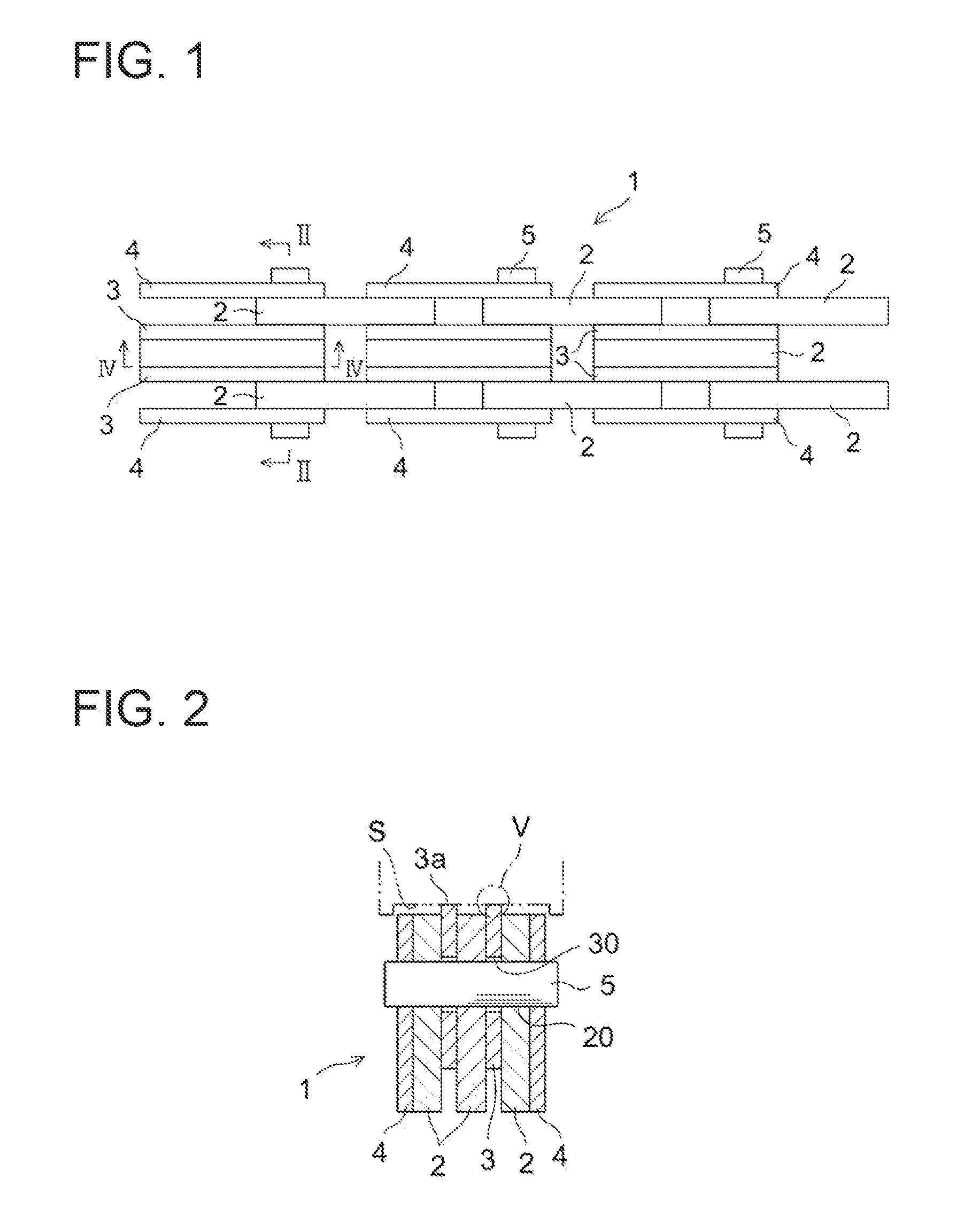
[0039]FIGS. 1 to 5 illustrate the silent chain according to the first exemplary embodiment, and symbols which are the same in these figures indicate components which are the same or corresponding.

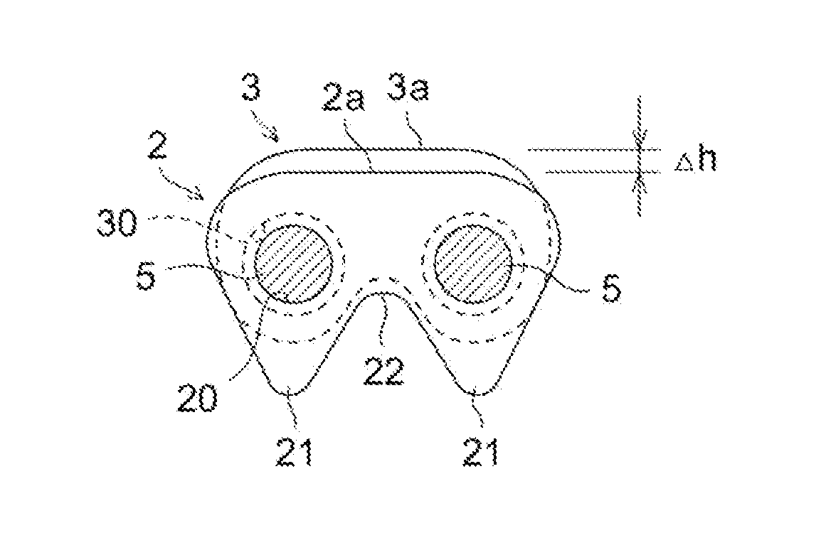
[0040]As shown in FIGS. 1 to 3, a silent chain 1 has a configuration in which a large number of links 2 each having a pair of pin holes 20 and each having a pair of tooth parts 21 which mesh with sprockets (not depicted) are arranged in the chain length direction (the horizontal direction in FIG. 1) and the chain width direction (the vertical direction in FIG. 1), and the links 2 are linked so as to be able to pivot about one another by linking pins 5 which are inserted into the pin holes 20.

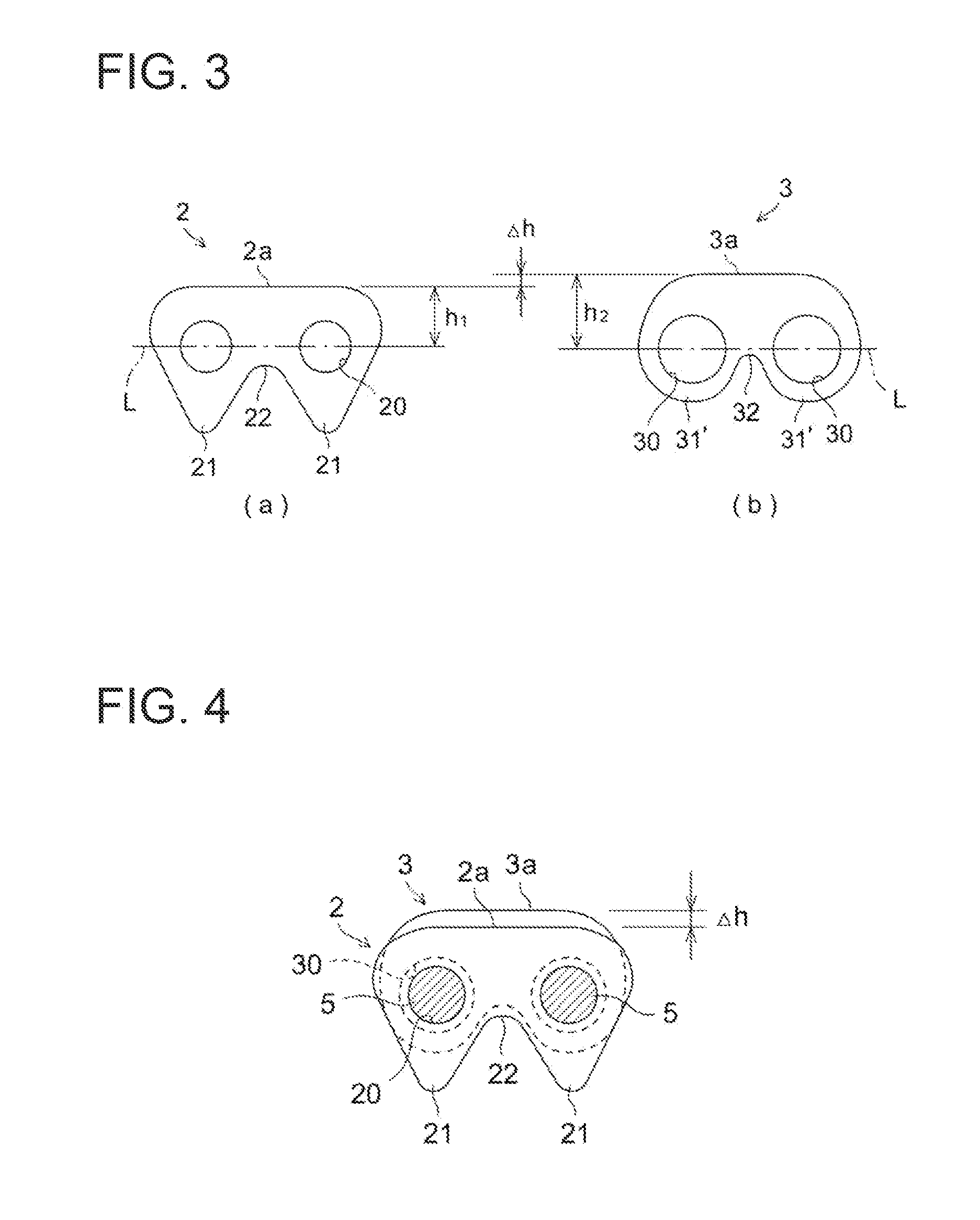
[0041]The tooth parts 21 of the links 2 are linked by means of a crotch part 22. The links 2 have a substantially flat back surface part 2a. The links 2 have a back surface height h1 which is defined by the distance from the pin hole center line L passing through the center of each pair of pin holes 20 ...

second exemplary embodiment

[0055]An example was described above in the first exemplary embodiment in which the sliding plates 3 are arranged in the central part of the guide link row, but this does not limit the application of the present invention. The sliding plates 3 may equally be arranged at both ends of the guide link rows.

[0056]FIGS. 6 and 7 show the silent chain according to the second exemplary embodiment of the present invention. It should be noted that in these figures, symbols which are the same in the first exemplary embodiment indicate components which are the same or corresponding.

[0057]As shown in FIGS. 6 and 7, the sliding plates 3 are arranged on the inside of the guide links 4 at both ends of a silent chain 1′. The sliding plates 3 overlie the inner surface of the guide links 4.

[0058]The sliding plates 3 have a pair of pin holes 30 into which the linking pins 5 are inserted, the diameter of the pin holes 30 is greater than the diameter of the pin holes 20 in the links 2, and the pin holes 3...

exemplary embodiment 1

Other Exemplary Embodiment 1

[0067]In each of the exemplary embodiments described above, the sliding plates 3 are formed with the pair of expanded parts 31′ which have the crotch part 32 therebetween, as shown in FIG. 3(b), but this does not limit the application of the present invention. Rather than forming the crotch part 32, the expanded parts 31′ may be linked by a flat surface or a curved surface. In this case, the overall shape of the sliding plates 3 becomes oval or rectangular.


PUM


Abstract

To provide a silent chain which makes it possible to further reduce friction loss during operation and to enhance operating efficiency, while also making it possible to reliably prevent assembly errors. A silent chain 1 in which a plurality of links 2 each having a pair of tooth parts 21 which mesh with sprockets and a pair of pin holes 20 are arranged in the lengthwise direction and thickness direction and are linked so as to be able to pivot about one another by linking pins 5 which are inserted into the pin holes 20, and sliding plates 3 are provided. The sliding plates 3 have a pair of pin holes 30 into which the linking pins 5 are inserted, and also have a back surface part 3a which has a greater back surface height h2 than the back surface height h1 of the links 2 and comes into contact with a tensioner arm or chain guide. The sliding plates 3 do not have tooth parts which mesh with the sprockets.

Description

TECHNICAL FIELD[0001]The present invention relates to a silent chain, and more specifically it relates to an improved structure for enhancing operating efficiency by further reducing friction loss during operation.PRIOR ART[0002]Silent chains are used as power transmission chains and timing chains in automobiles and motorcycles etc. Silent chains generally have a configuration in which a large number of links each having pairs of tooth parts and pin holes are linked together in a pivotable manner by linking pins which are inserted into each of the pin holes.[0003]Furthermore, silent chains are wound around a drive sprocket and a driven sprocket during use, and between the drive sprocket and the driven sprocket a tensioner arm which is urged toward the chain side by means of a tensioner is disposed on the slack-side span of the silent chain, while a chain guide for guiding the travel of the silent chain is disposed on the tension-side span of the silent chain.[0004]When the silent ch...

Claims


Application Information

Patent Timeline
IPC IPC(8): F16G13/04
CPCF16G13/08F16G13/04F16G15/00F16G15/12
Inventor YOSHIDA, YUKIOEDA, JUNICHI
Owner BORGWARNER INC
Why Eureka
Try Eureka