
Observation valve structure

Active Publication Date: 2012-06-28
Y S VALVE MFG
View PDF3 Cites 16 Cited by
  • Summary
  • Abstract
  • Description
  • Claims
  • Application Information

AI Technical Summary

Benefits of technology

[0006]A further object of the present invention is to provide an observation valve structure which provides an annular gasket received in the stop trough of the inlet pipe joint and another annular gasket at the other end of the ball shutter to clamp the ball shutter tightly, providing a better airtight function. The two annular gaskets are uniform specification. The guide groove and the guide holes of the inlet pipe joint facilitate the generation of air bubbles. The same parts can be replaced with ease.

Problems solved by technology

If the conical connecting body is a resilient body, its structure is not strong enough and deformed easily.
The three-way ball shuttle is wearing easily and the specific parts are not common to increase the cost.
When the elastic member in the positioning bead is fatigued, it is easily displaced by an external force.

Method used


Image

  • Observation valve structure
  • Observation valve structure
  • Observation valve structure

Examples


Embodiment Construction

[0019]Embodiments of the present invention will now be described, by way of example only, with reference to the accompanying drawings.

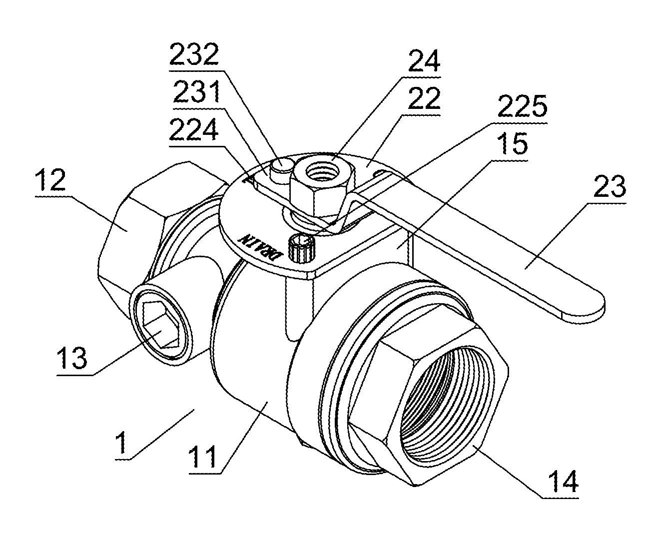
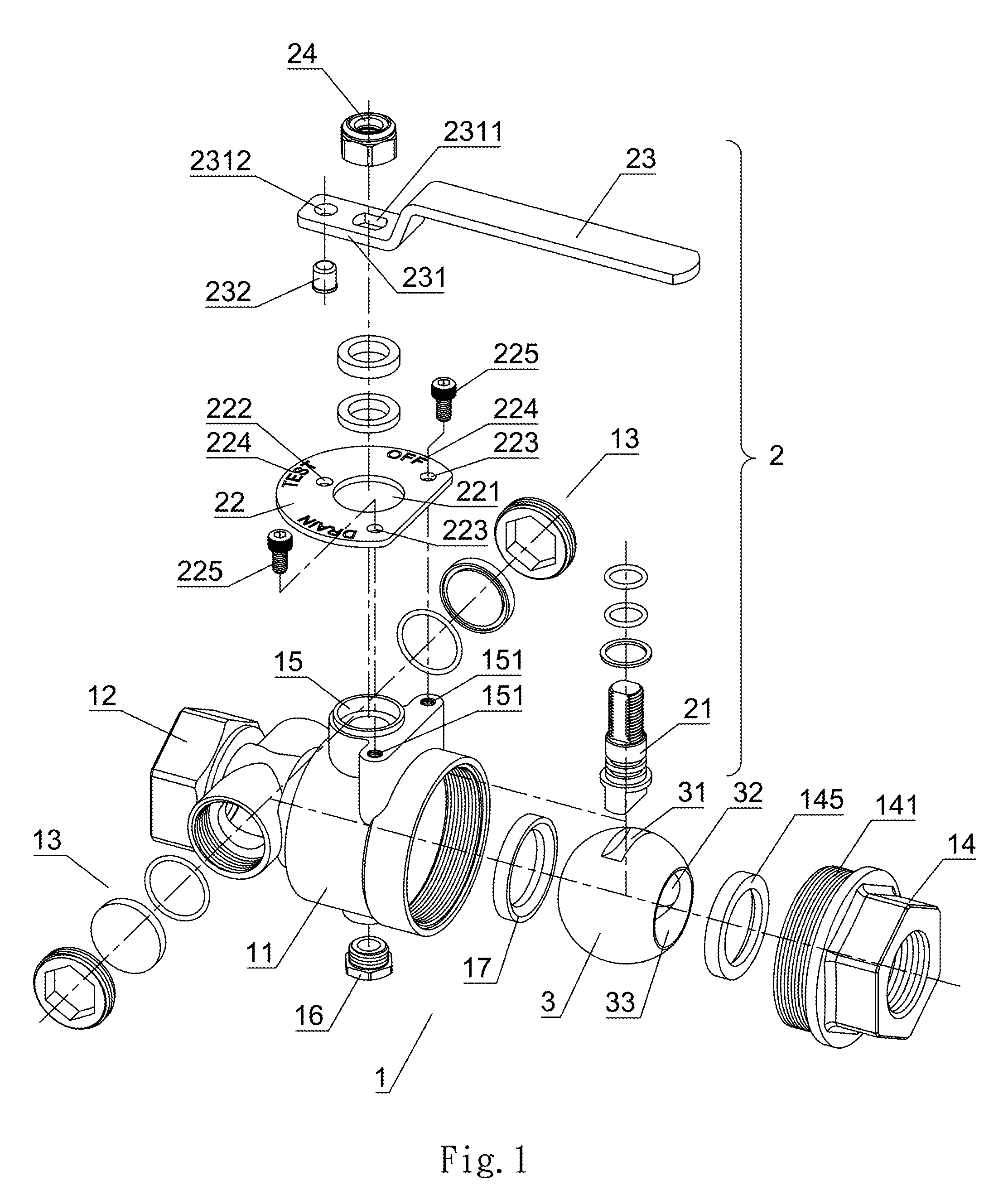
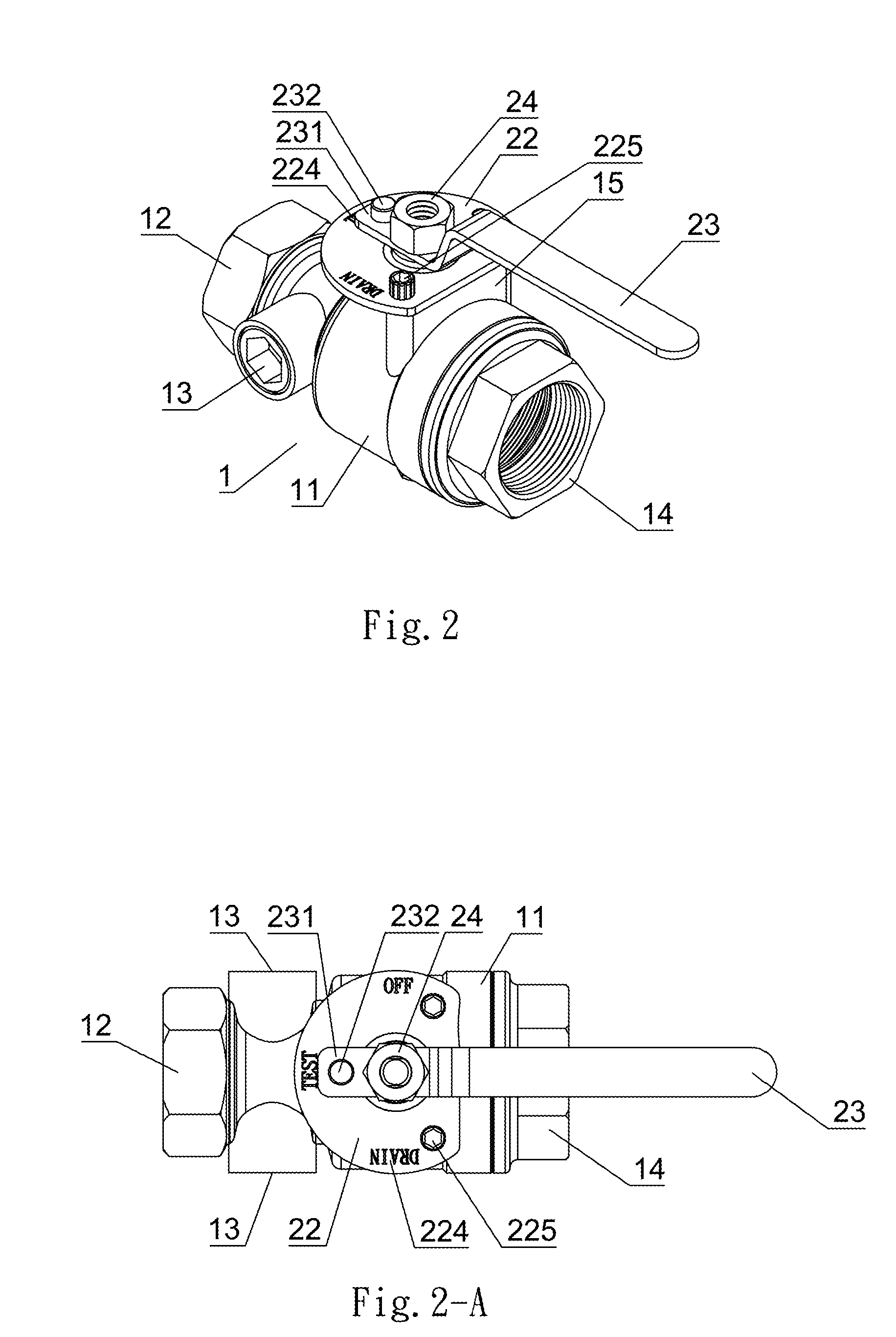
[0020]As shown in FIG. 1, FIG. 2, FIG. 4, FIG. 1-A, FIG. 4-A, an observation valve structure according to a preferred embodiment of the present invention comprises a pipe connector 1 which is composed of a connector body 11, an outlet pipe joint 12 at an outlet end of the connector body 11, two observation mirror assemblies 13, and an inlet pipe joint 14 at an inlet end of the connector body 11. The pipe connector 1 comprises a driving shaft assembly 2 and a ball shutter 3 which is disposed in the connector body 11 and driven by the driving shaft assembly 2.

[0021]The pipe connector 1 comprises an annular gasket 17 at the outlet end of the connector body 11. The outlet pipe joint 12 is connected to the outlet end of the connector body 11. The two observation mirror assemblies 13 are located at two sides of the connector body 11. The inlet pipe joint 14...


PUM


Abstract

An observation valve structure includes an inlet pipe joint. The inlet pipe joint has an outer threaded section at an inner end thereof, an annular guide groove in the inlet pipe joint, and guide holes at the inner end thereof. The annular guide groove communicates with the guide holes. The inlet pipe joint has a stop trough at the inner end thereof for insertion of an annular gasket. A holder is provided on top of the connector body. The holder has two threaded holes at two sides thereof close to the inlet end of the connector body. A plate is positioned on the holder by two screws which are screwed in the threaded holes. The plate has a top surface with characters which are perpendicular to each other, a position hole disposed close to the middle character, and two apertures disposed at an outer side of the other two characters for insertion of the two screws. The handle has an indication plate. The indication plate has a positioning bead hole for insertion of a positioning bead. Through the right side or the left side of the indication plate limited by the screws or the positioning bead slid into the positioning bead hole and stopped, the handle cooperates with the characters of the plate to control rotation of the ball shutter. Two opposing sides of the ball shutter are airtight through two uniform annular gaskets which can be replaced with ease. The present invention can limit and position the handle and enhance side water flow.

Description

BACKGROUND OF THE INVENTION[0001]1. Field of the Invention[0002]The present invention relates to an observation valve structure, and more particularly to one having an inlet pipe joint. The inlet pipe has an outer threaded section at an inner end thereof, an annular guide groove in the inlet pipe joint, and guide holes at the inner end thereof. The annular guide groove communicates with the guide holes. The inlet pipe joint has a stop trough at the inner end thereof for insertion of an annular gasket which is used to clamp one side of a ball shutter. A plate and a handle are pivotally connected to a holder. The handle has an indication plate and a positioning bead and the plate has a positioning hole and two threaded holes to limit and position the handle and to enhance side water flow.[0003]2. Description of the Prior Art[0004]A conventional observation valve, referring to U.S. Pat. No. 6,196,262, comprises a conical connecting body. The center of the conical connecting body has a ...

Claims


Application Information

Patent Timeline
IPC IPC(8): F16K5/06F16L21/00
CPCF16K37/0058F16K5/0605Y10T137/8309Y10T137/8359Y10T137/86743
Inventor WANG, CHI-YUAN
Owner Y S VALVE MFG
Learn More