Bidirectional shift register and image display device using the same

a technology of image display device and shift register, which is applied in the direction of digital storage, instruments, computing, etc., can solve problems such as unstable operation, and achieve the effect of stable shift operation

Active Publication Date: 2012-06-28
JAPAN DISPLAY INC
View PDF9 Cites 26 Cited by
  • Summary
  • Abstract
  • Description
  • Claims
  • Application Information

AI Technical Summary

Problems solved by technology

However, when the bidirectional shift register adopting the unit register circuit as stated above is continuously driven in one direction, the threshold voltage of the switch element shifts in the negative direction, and the operation can become unstable.

Method used


Image

  • Bidirectional shift register and image display device using the same
  • Bidirectional shift register and image display device using the same
  • Bidirectional shift register and image display device using the same

Examples


embodiment 1

[0066]FIG. 3 is a circuit view of the n-th unit register circuit 38 (on the side of the gate line drive circuit 14R) of the bidirectional shift register 30 of embodiment 1. First, the basic structure of the n-th unit register circuit 38 as the main stage will be described with reference to FIG. 3, and then, the structure of the unit register circuits 38 of the first stage, the third stage, the (n+2)-th stage and the (n+4)-th stage as the dummy stages will be described while attention is mainly given to different points from the basic structure.

[0067]The n-th unit register circuit 38 includes n-channel transistors T1F, T1B, T2 to T6, T7F, T7B, T9F and T9B, and capacitors C1 and C3.

[0068]The n-th unit register circuit 38 includes an output terminal NOUT(n) to output its own pulse G(n), and includes a forward direction set terminal NSF(n), a backward direction set terminal NSB(n), a forward direction reset terminal NRF(n) and a backward direction reset terminal NRB (n), which are termi...

embodiment 2

[0121]Hereinafter, the same component as that of embodiment 1 is denoted by the same reference numeral, and the explanation already made on the component is used in order to simplify the explanation.

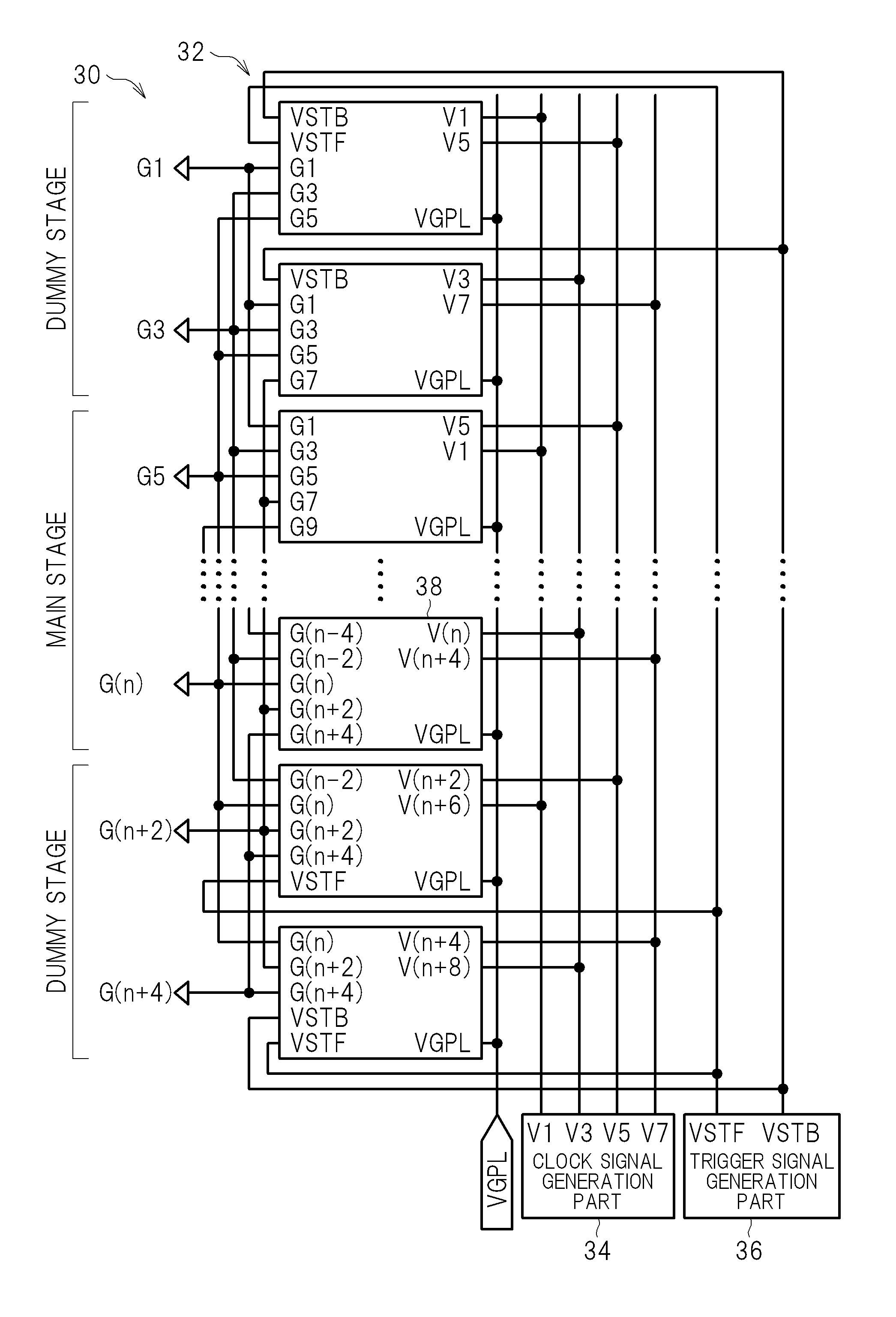
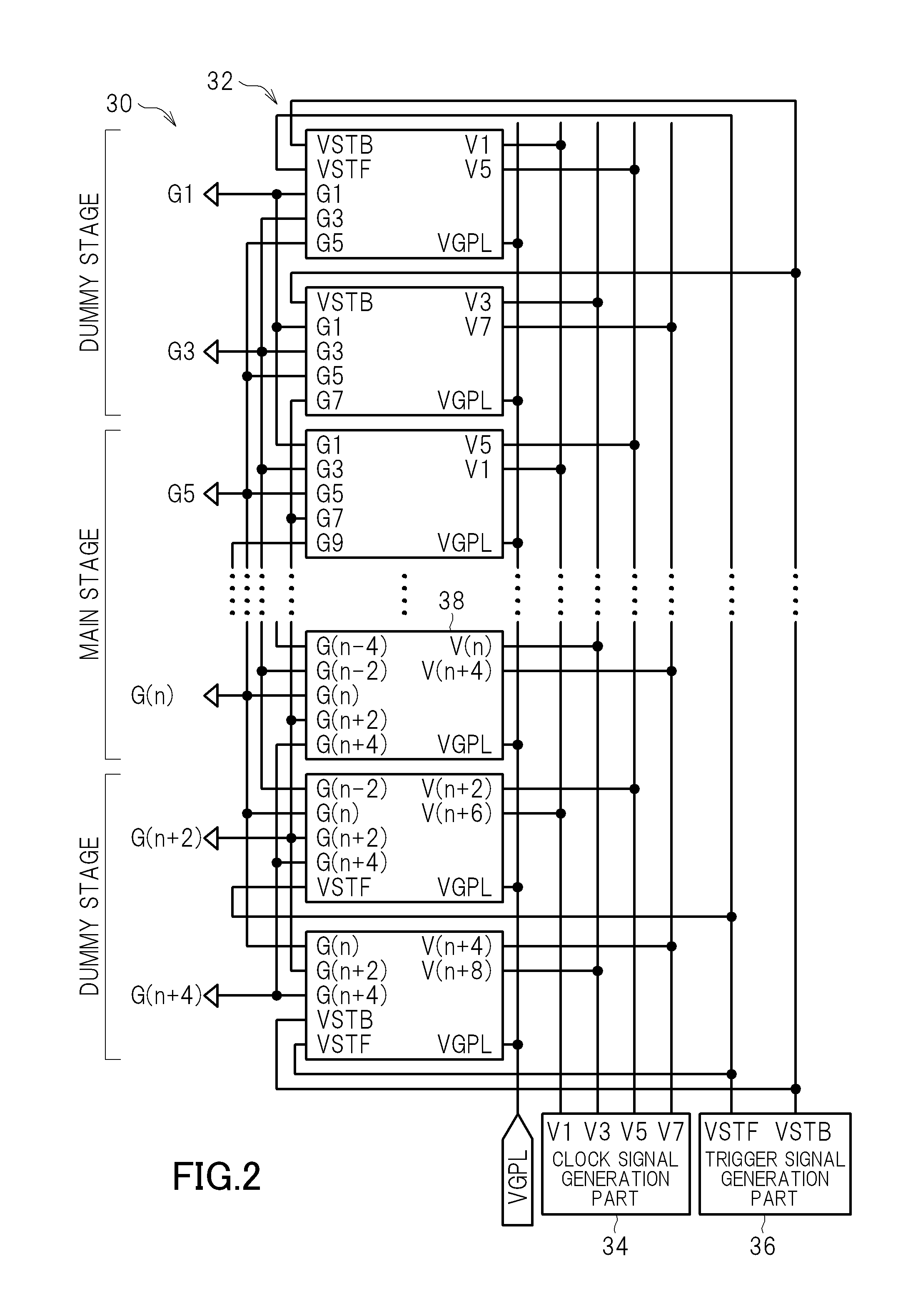
[0122]FIG. 12A to FIG. 12E are circuit views each showing a unit register circuit 38 (on the side of a gate line drive circuit 14R) of a bidirectional shift register 30 of embodiment 2. FIG. 12A shows a unit register circuit 38 of a first stage, FIG. 12B shows a unit register circuit 38 of a third stage, FIG. 12C shows a unit register circuit 38 of an n-th stage (equal to FIG. 3), FIG. 12D shows a unit register circuit 38 of an (n+2)-th stage, and FIG. 12E shows a unit register circuit 38 of an (n+4)-th stage. As shown in FIG. 2, among these, the first stage and the third stage are the top dummy stages, the n-th stage is the last stage of the main stages, and the (n+2)-th and the (n+4)-th stages are the rear dummy stages.

[0123]The unit register circuit 38 of embodiment 2 is different fro...


PUM


Abstract

A bidirectional shift register capable of performing a stable shift operation in both directions and an image display device using the same are provided. In forward shift operation, when reference point N1 is at H level, (n+4)-th unit register circuit as a rear stage of the bidirectional shift register outputs pulse G(n+4) in synchronization with clock pulse V (n+4) inputted to (n+4)-th unit register circuit. A backward direction trigger signal VSTB is generated not only at the time of start of backward shift, but also, for example, in period (time t4 to t5) of one-phase clock immediately after G(n+4) is outputted in vertical blanking interval of the forward shift. The backward direction trigger signal VSTB is inputted to gate of a transistor provided to set reference point N1 of (n+4)-th unit register circuit to H level at the time of start of the backward shift.

Description

CROSS-REFERENCE TO RELATED APPLICATION[0001]The present application claims priority from Japanese application JP 2010-293639 filed on Dec. 28, 2010, the content of which is hereby incorporated by reference into this application.BACKGROUND OF THE INVENTION[0002]1. Field of the Invention[0003]The present invention relates to a bidirectional shift register capable of changing the output sequence of pulses and an image display device using the same to drive each of scanning lines.[0004]2. Description of the Related Art[0005]The improvement in resolution of an image display device is realized by the improvement in arrangement density of pixels of a display part. Along with that, the arrangement pitch of various signal lines to supply signals to pixel circuits becomes narrow. Gate lines provided as scanning lines of pixels are connected to a gate line drive circuit on the side of a display area. The gate line drive circuit includes a shift register to sequentially output voltages, which e...

Claims


Application Information

Patent Timeline
Patent Type & Authority Applications(United States)
IPC IPC(8): G09G5/00G11C19/00
CPCG11C19/287G09G2310/0286G09G3/3677G09G5/003G09G2310/08G09G2330/021
Inventor OCHIAI, TAKAHIROGOTO, MITSURUHIGASHIJIMA, HIROYUKIKOTANI, YOSHIHIROMATSUMOTO, SHUUICHIROU
Owner JAPAN DISPLAY INC
Why Eureka
Try Eureka