Blur detection with local sharpness map

a local sharpness and blur detection technology, applied in the field of single-ended blur detection methods, can solve the problems of lack of sharpness or blurring, video image sequences that look less sharp than others, and up-converted sd video frame content does not provide the detail or sharpness to the full potential of hd resolution

Active Publication Date: 2012-06-28
PROJECT GIANTS LLC
View PDF6 Cites 45 Cited by
  • Summary
  • Abstract
  • Description
  • Claims
  • Application Information

AI Technical Summary

Benefits of technology

[0008]The maximum difference value between the decimated arrays, multiplied by another weighting factor, is compared with the difference value between the decimated arrays to produce a sharpness overlay map which is used to mark the original monochrome image or field / frame with a color to indicate areas used to determine the blur value. Also for images having horizontal and vertical blockiness artifacts not in the original image, the horizontal and vertical filters outputs are disabled for blur detection. Alternatively, to detect the blockiness artifacts separate from blur, a set of fast edge filters is used without diagonal filters, and the horizontal and vertical absolute filter outputs are combined and decimated, and the diagonal absolute filter outputs are also combined and decimated. The ratio of the decimated arrays are compared with a threshold to generate a tiling flag when blockiness artifacts occur, which flag may be used to disable the horizontal and vertical filters adaptively for the blur measurement. Finally the local sharpness maximum, or log of the localized maximum sharpness value, may be compared with a sharpness threshold and, if the logLMS value is less than the sharpness threshold for a period of time, an up conversion flag is set to indicate that the image is up-converted from a lower resolution image.

Problems solved by technology

There have been customer complaints that some video image sequences look less sharp than others.
Such lack of sharpness, or blurring, may be caused by over-compression due to loss of detail resulting from tiling, i.e., coarse pixelation, or de-blocking filters in H.264 compression coders / decoders (CODECs) that remove horizontal and vertical edges which typically further blurs the video image sequence.
Therefore the up-converted SD video frame content does not provide the detail or sharpness to the full potential of the HD resolution, i.e., the HD video looks soft or blurred.
Prior blur or soft image detection methods are overly sensitive to noise, such that noise within the video images reduces the assigned blur value even though the image still appears soft or blurry.

Method used


Image

  • Blur detection with local sharpness map
  • Blur detection with local sharpness map
  • Blur detection with local sharpness map

Examples


Embodiment Construction

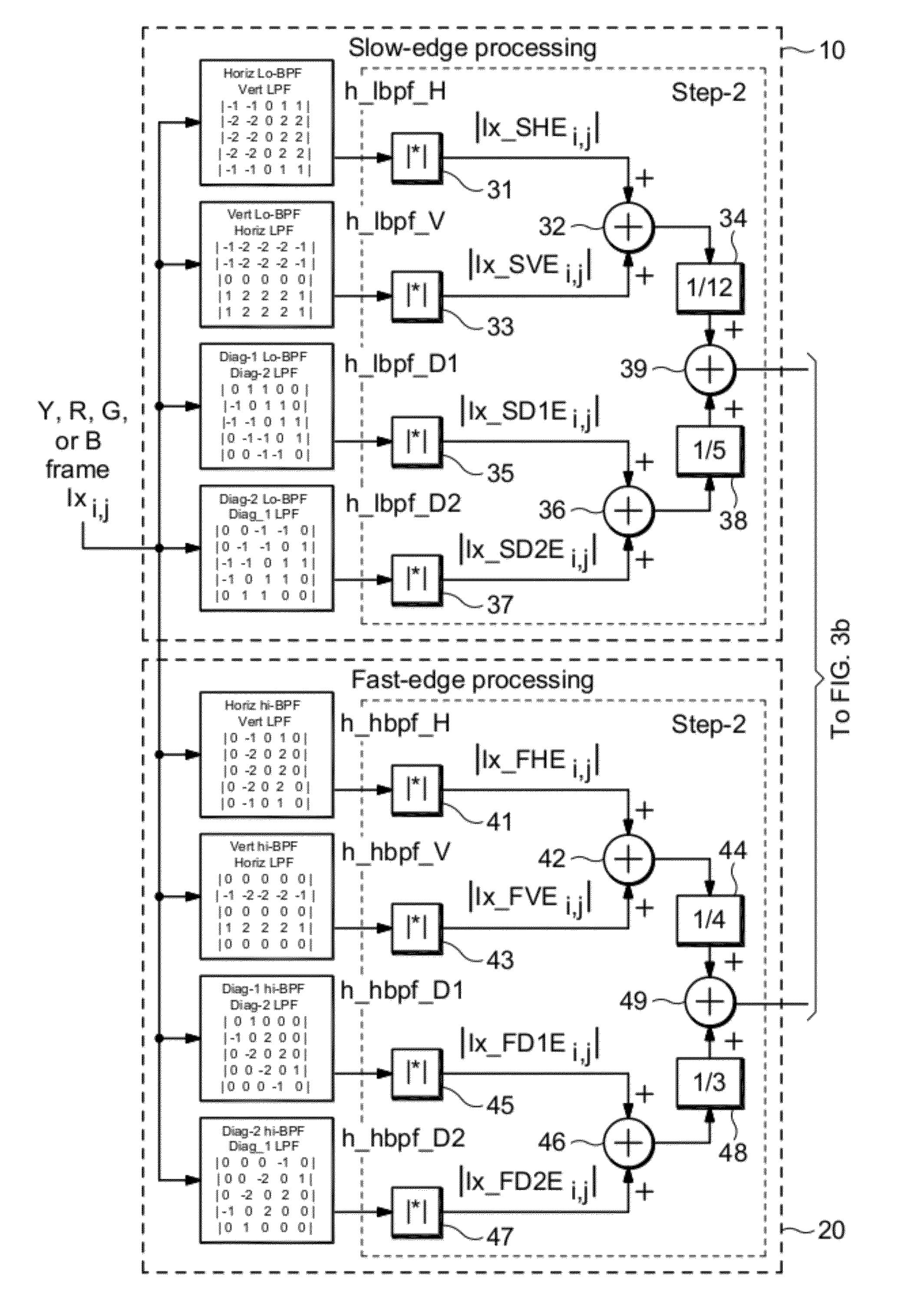
[0017]The basic concept used in the present invention is that image sharpness is related to the transition-width or “speed” of edges of objects in the spatial directions which make up the subjective or perceived detail of the image. Blurred or soft images still contain edges defining the image objects, but with relatively longer edge transitions ranging over more pixels in one or more spatial directions. The longer edge transitions may be the result of poor focus, motion-blur during image capture, image compression or noise reduction filtering, or compression de-blocking filtering by HD CODECs. Detection of the edge-widths or edge-speeds of the image objects in a sequence of fields / frames is done in a way to create a normalized ratio of higher spatial frequencies (fast edges=sharp edges) to lower spatial frequencies (slow edges=blurred edges). The assumption is that, for a given image pixel resolution, an image that appears relatively soft or blurred has a lower ratio of high freque...


PUM


Abstract

A single-ended blur detection probe and method with a local sharpness map for analyzing a video image sequence uses two sets of edge filters, one for “fast edges” and the other for “slow edges.” Each set of edge filters includes a horizontal bandpass filter, a vertical bandpass filter and a pair of orthogonal diagonal filters where the frequency response of the fast edge filters overlap the frequency response of the slow edge filters. The video image sequence is input to each filter of each set, and the output absolute values are combined with weighting factors to produce a slow edge weighted sum array and a fast edge weighted sum arra. The respective weighted sum arrays are then decimated to produce a slow edge decimated array and a fast edge decimated array. The ratio of the maximum difference value between the decimated arrays and the maximum value from the fast edge decimated array, weighted by an appropriate factor, produces a localized maximum sharpness value, the log of which produces a dimensionless blur value.

Description

BACKGROUND OF THE INVENTION[0001]The present invention relates to video quality measurements, and more particularly to a single-ended blur detection method to determine overall sharpness of a scene in a video image sequence.[0002]Television broadcasters are interested in determining the quality of a video image sequence that is distributed over Internet Protocol (IP) and radio frequency (RF) broadcast networks. Recently broadcasters have become concerned about the sharpness or, conversely, the blur in video image sequences. There have been customer complaints that some video image sequences look less sharp than others. Such lack of sharpness, or blurring, may be caused by over-compression due to loss of detail resulting from tiling, i.e., coarse pixelation, or de-blocking filters in H.264 compression coders / decoders (CODECs) that remove horizontal and vertical edges which typically further blurs the video image sequence. This may also be caused by up-conversion of the video image se...

Claims


Application Information

Patent Timeline
Patent Type & Authority Applications(United States)
IPC IPC(8): H04N5/00G06K9/40
CPCH04N17/004G06T7/0002H04N5/21G06T2207/30168H04N5/14G06T7/0085G06T7/13
Inventor BAKER, DANIEL G.
Owner PROJECT GIANTS LLC
Why Eureka
Try Eureka