Multi-band channel capacity for meter network

a multi-band channel and network technology, applied in data switching networks, frequency-division multiplexes, wireless architecture usage, etc., can solve problems such as system dropout and unwound, and achieve the effect of reducing the signal to noise ratio (snr) and ensuring service quality

Active Publication Date: 2012-06-28
SENSUS USA
View PDF10 Cites 12 Cited by
  • Summary
  • Abstract
  • Description
  • Claims
  • Application Information

AI Technical Summary

Benefits of technology

[0005]The present disclosure relates to a system and method for controlling the communication of data between a multiplicity of endpoints (sometimes water gas or electricity meters, load controllers, PCT, utility displays, or the like) contained within a communication system and a single tier of intermediate gateways. The system optimizes the communication channel used to transmit the data between the meters and the gateways to ensure that each of the meters is transmitting data at the maximum rate while at the same time insuring a minimum “quality of service” and reliably, even to endpoints that in locations which are hard to reach and thus have lower signal to noise ratio (SNR).
[0006]During initial installation of meters in the communication system, each meter is initially assigned a default communication channel over which communications between the meter and the gateway will take place. The default communication channel is selected to have relatively long message duration since the signal-to-noise ratio between the meter and the gateway is initially unknown and the longer message duration improves link margin SNR.

Problems solved by technology

Therefore, although the operator may attempt to optimize the system upon deployment, if physical characteristics of the area change or if other variables are modified, the system will drop out of optimization, which is not desired.

Method used


Image

  • Multi-band channel capacity for meter network
  • Multi-band channel capacity for meter network
  • Multi-band channel capacity for meter network

Examples


Embodiment Construction

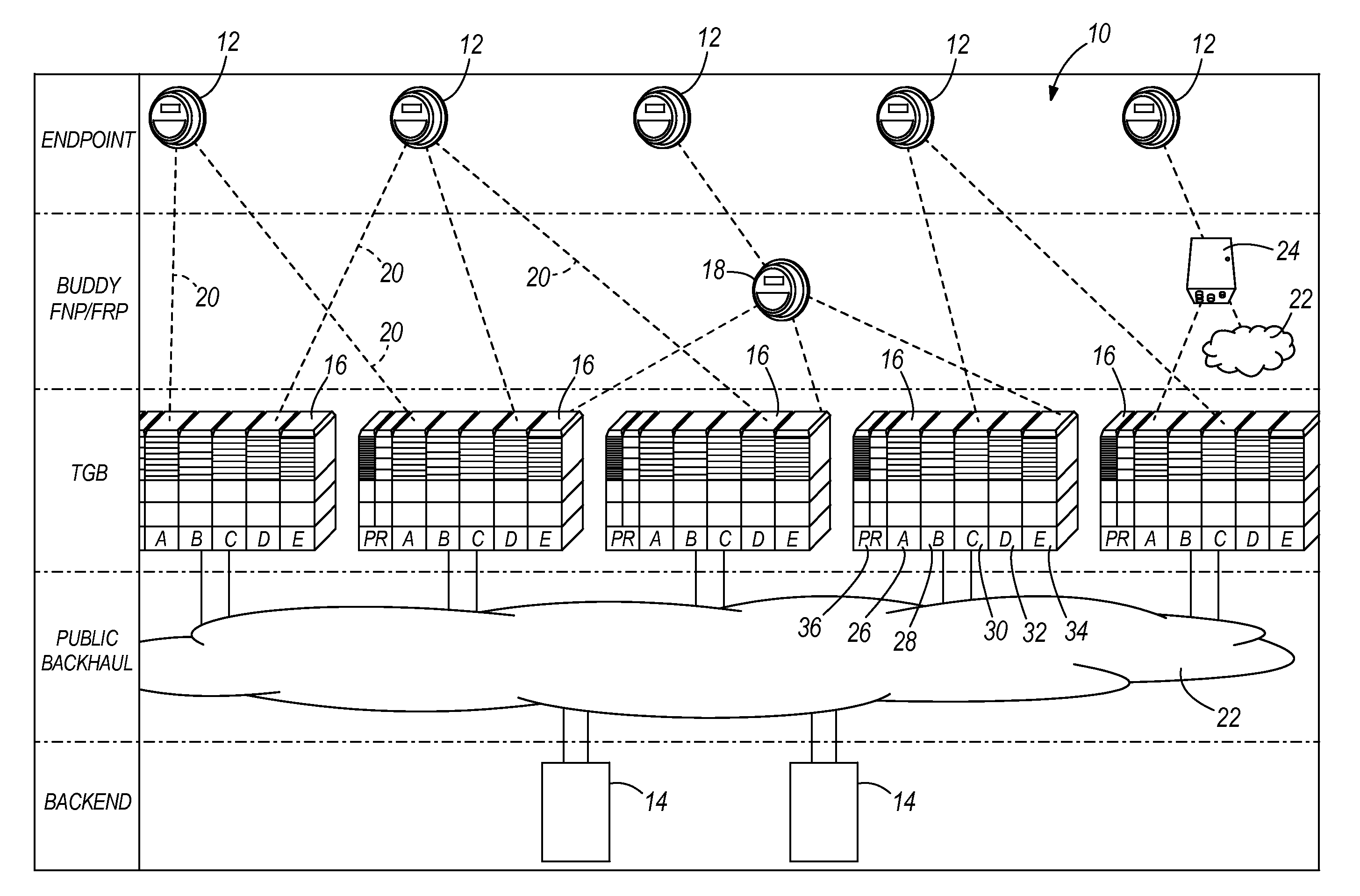
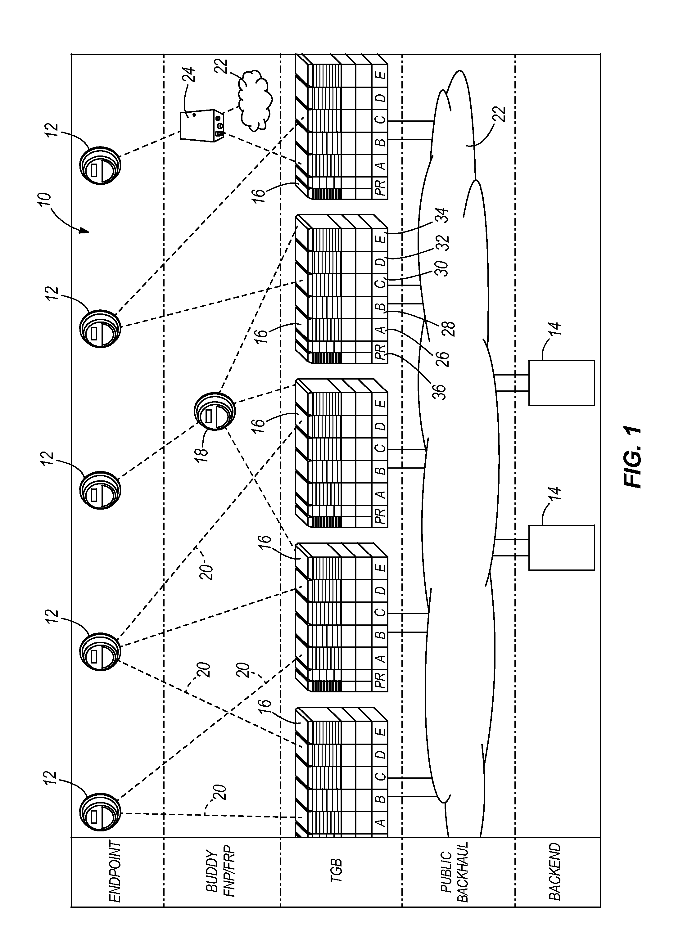
[0027]FIG. 1 illustrates a communication system 10 for communicating between a plurality of meters 12 and a back end data accumulation site or server 14. In the embodiment shown in FIG. 1, the meters 12 can be any type of utility meter, such as an electricity meter, gas meter, or water meter. The data accumulation server 14 can be located at a utility, third party data accumulation company or any other location that receives the accumulated meter data and processes the data for analysis, billing or any other purpose. The communication system 10 shown in FIG. 1 could be the FlexNet® communication system available from Sensus USA. However, other different types of communication systems are contemplated as being within the scope of the present disclosure.

[0028]In the embodiment shown in FIG. 1, each of the meters 12 communicates information either to one of a plurality of gateways 16 or to an intermediate meter 18. The intermediate meter 18 relays information from each of the end point...


PUM


Abstract

A communication system that relays data messages from or to a plurality of remote endpoints via RF gateways to a data accumulation site over one of a series of communication channels. The communication system monitors the signal-to-noise ratio of communication from each individual endpoint, which can be utility meters and related control or monitoring points, to a gateway. Based upon a quality of service and / or the signal-to-noise ratio of the communication of the endpoints to the gateways, the system assigns a desired communication channel to the endpoint. Each of the desired communication channels have varying data transmission rate and required SNR and each channel is selected based upon the signal-to-noise ratio of the transmissions from the endpoint to the gateways. If the signal-to-noise ratio changes for an endpoint, the system dynamically reassigns a different channel to the meter based upon the updated signal-to-noise ratio.

Description

CROSS-REFERENCE TO RELATED APPLICATION[0001]The present application is based on and claims priority to U.S. Provisional Patent Application Ser. No. 61 / 426,746 filed Dec. 23, 2010.BACKGROUND OF THE INVENTION[0002]The present disclosure generally relates to a method of controlling the radio communication of data messages between a plurality of field endpoints (in some cases utility meters) and a network of fixed location gateways which in turn communicate with a centrally located network controller. More specifically, the present disclosure relates to a method that optimizes the use of the communication channels by each of the plurality of endpoints to increase the overall effective message transmission capacity and where needed to increase the direct reach between a gateway and endpoint, thus enabling single-tier communications.[0003]Presently, automated meter reading (AMR) systems exist that allow meters, such as electricity, gas and water meters, to communicate consumption informat...

Claims


Application Information

Patent Timeline
Patent Type & Authority Applications(United States)
IPC IPC(8): H04L12/56H04L12/26
CPCH04Q9/00H04W24/00H04W28/16H04W40/12H04Q2209/823H04Q2209/25H04Q2209/40H04Q2209/60H04W72/02H04L45/30H04L47/70
Inventor SANDERFORD, JR., H. BRITTON
Owner SENSUS USA
Why Eureka
Try Eureka