Eureka AIR delivers breakthrough ideas for toughest innovation challenges, trusted by R&D personnel around the world.

Electrical connector

Inactive Publication Date: 2012-06-28
DAIICHI SEIKO CO LTD
View PDF10 Cites 8 Cited by
  • Summary
  • Abstract
  • Description
  • Claims
  • Application Information

AI Technical Summary

Benefits of technology

[0019]Accordingly, it is an object of the present invention to provide an electrical connector used for connecting electrically a flat circuit device, such as an FPC or an FFC, with a solid circuit board, which comprises a housing provided thereon with an opening through which a flat circuit device is inserted into the housing, a plurality of conductive contacts provided to be arranged on the housing and a conductive shell member covering partially the housing, and which avoids the aforementioned disadvantages encountered with the prior art.
[0020]Another object of the present invention is to provide an electrical connector used for connecting electrically a flat circuit device, such as an FPC or an FFC, with a solid circuit board, which comprises a housing provided thereon with an opening through which a flat circuit device is inserted into the housing, a plurality of conductive contacts provided to be arranged on the housing and a conductive shell member covering partially the housing, and in which the flat circuit device inserted in the housing can be put in holding by a holding member formed in the conductive shell member to be surely prevented from getting out of the housing unwillingly and then released from the holding by the holding member to be able to get out of the housing with a structure in which the electrical connector can be miniaturized on the whole and the number of structural parts can be reduced.
[0021]A further object of the present invention is to provide an electrical connector used for connecting electrically a flat circuit device, such as an FPC or an FFC, with a solid circuit board, which comprises a housing provided thereon with an opening through which a flat circuit device is inserted into the housing, a plurality of conductive contacts provided to be arranged on the housing and a conductive shell member covering partially the housing, and in which the flat circuit device inserted in the housing can be easily released from holding by a holding portion formed in the conductive shell member with a considerably simple manipulation to a releasing portion formed in the conductive shell member.

Problems solved by technology

In the case of the previously proposed electrical connector which has the holding means operative to shift its position in response to the rotational movements of the actuator provided to be rotatable in regard to the housing, it is required that the holding means and the actuator are provided as separate parts independent from each other and this results in problems or disadvantages that miniaturization in the electrical connector is undesirably hindered, the number of constitutive parts of the electrical connector increases undesirably, and a production cost of the electrical connector rises disagreeably.
Besides, it is necessary, for causing the holding means to engage with or disengage from the flat circuit device inserted in the housing, to rotate the actuator in regard to the housing and this results in undesirable increase in an open space around the electrical connector.
In the case of the previously proposed electrical connector which has the conductive shell member provided to be rotatable in regard to the housing and the holding means formed in the part of the conductive shell member, since the conductive shell member is operative to rotate in regard to the housing, any part of the conductive shell member not be used for fastening the electrical connector to the solid circuit board so that a separate holding-down member for fastening the electrical connector to the solid circuit board is required and this results in problems or disadvantages that miniaturization in the electrical connector is undesirably hindered, the number of constitutive parts of the electrical connector increases undesirably, and a production cost of the electrical connector rises disagreeably.

Method used


Image

  • Electrical connector
  • Electrical connector
  • Electrical connector

Examples


Embodiment Construction

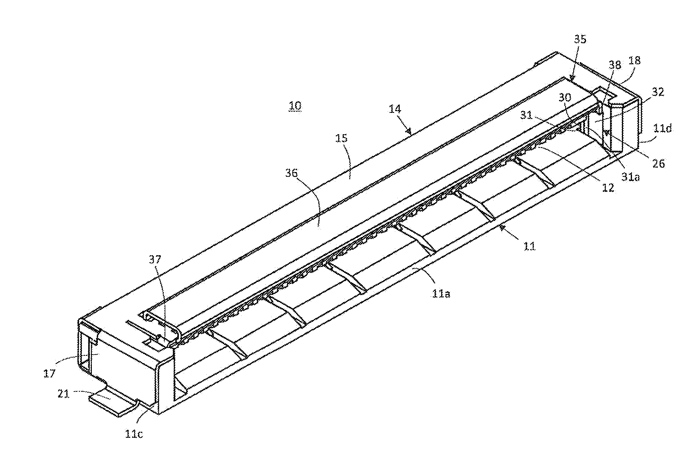
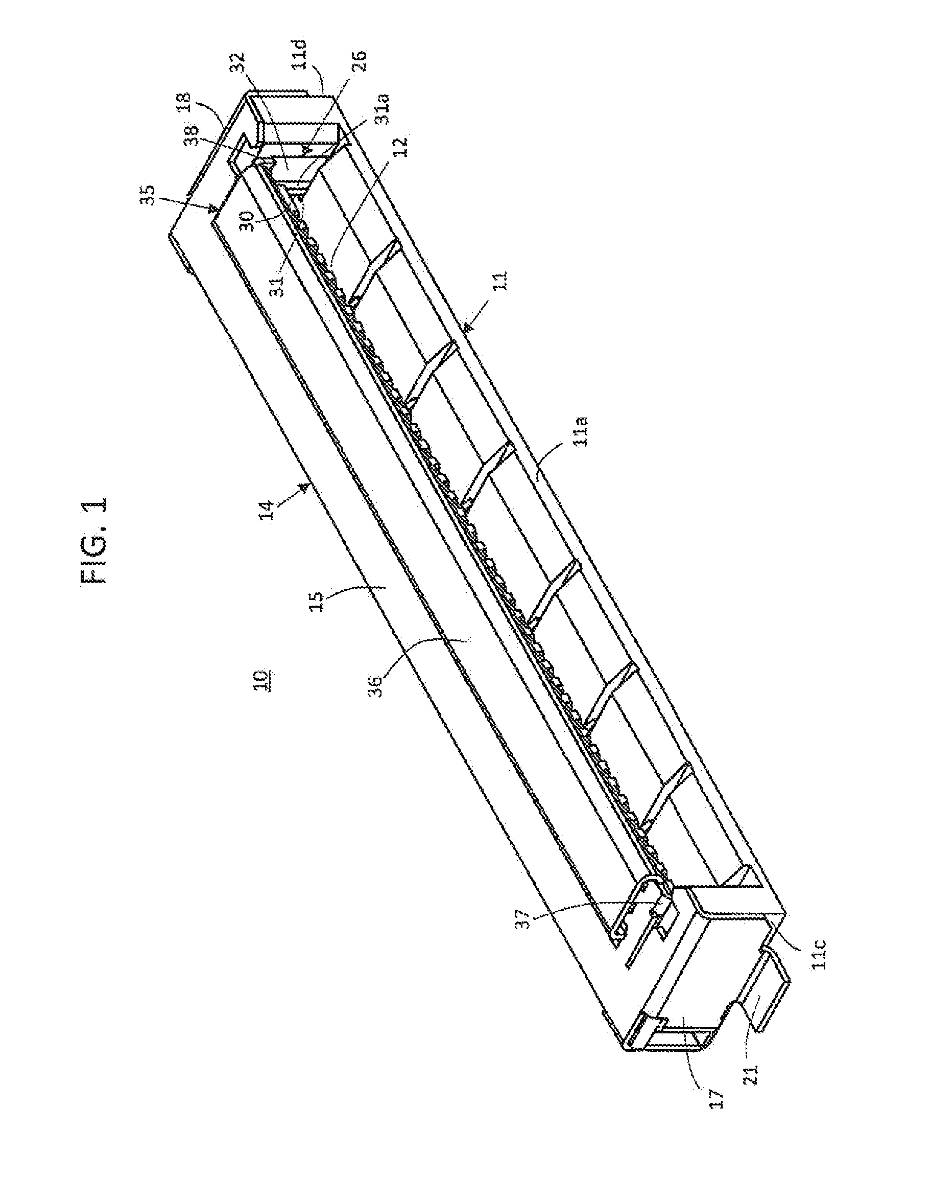
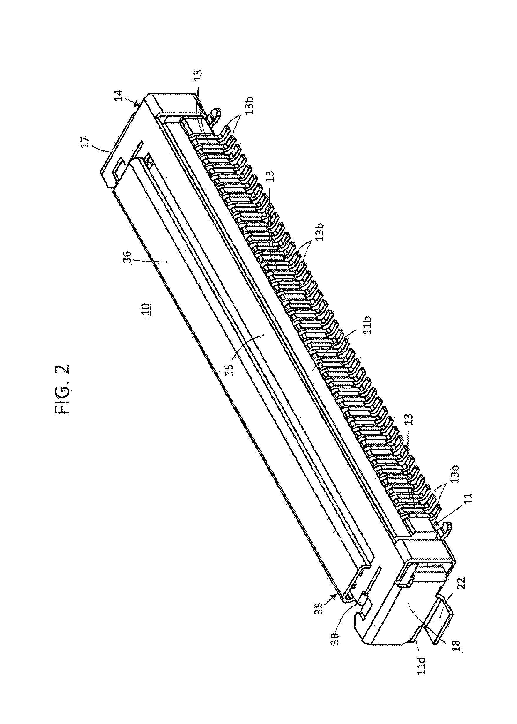
[0053]Each of FIG. 1 which is a schematic front, top and left side perspective view, FIG. 2 which is a schematic rear, top and right side perspective view, FIG. 3 which is a schematic plan view, FIG. 4 which is a schematic front view and FIG. 5 which is a schematic bottom view, shows an embodiment of electrical connector according to the present invention.

[0054]Hereinafter, for the sake of clear explanations, upper, lower, left and right sides of a front view shown in FIG. 4 are referred to as upper or top, lower or bottom, left and right portions or parts, respectively.

[0055]Referring to FIGS. 1 to 5, an electrical connector 10, which constitutes the embodiment of electrical connector according to the present invention, has a housing 11 made of, for example, insulator such as plastics or the like. The housing 11 has a front end portion 11a and a rear end portion 11b which constitute a first pair of opposite end portions of the housing 11, and a left side end portion 11c and a right...


PUM


Abstract

An electrical connector including a housing having an opening through which an FPC is inserted into the housing, conductive contacts arranged on the housing for contacting with signal connecting terminals on the FPC, and a conductive shell member mounted on the housing and provided therein with a holding portion for holding the FPC inserted in the housing and a releasing portion for releasing the FPC from holding by the holding portion, wherein the holding portion extends into the housing from an end wall portion of the conductive shell member covering a side end portion of the housing to engage with the FPC and the releasing portion is movable in an operating direction intersecting a direction of arrangement of the conductive contacts and provided thereon with an engaging projection for engaging with the holding portion to release the same from the engagement with the FPC.

Description

BACKGROUND OF THE INVENTION[0001]1. Field of the Invention[0002]The present invention relates generally to an electrical connector, and more particularly to an improvement in an electrical connector which has a housing, holding means for engaging with a flat circuit device, such as a flexible printed circuit board (hereinafter, referred to as an FPC) or a flexible flat cable assembly (hereinafter, referred to as an FFC) inserted in the housing, so as to hold the same to be prevented from getting out of the housing unwillingly, and a plurality of conductive contacts provided for coming into contact with connecting terminals provided on the flat circuit device so as to put the flat circuit device in electrical connection with another electrical device, such as a solid circuit board.[0003]2. Description of Related Art including information disclosed under 37 CFR 1.97 and 37 CFR 1.98[0004]A flat circuit device, such as a relatively small-sized FPC or FFC, used in various kinds of electr...

Claims


Application Information

Patent Timeline
IPC IPC(8): H01R9/03
CPCH01R12/772H01R12/79H01R13/6594H01R13/6271H01R13/6582H01R12/88H01R12/77H01R13/629
Inventor OZEKI, KOSUKE
Owner DAIICHI SEIKO CO LTD
Why Eureka
Eureka Blog
Learn More