Wire Stripping Device

a technology of stripping device and insulation jacket, which is applied in the field of self-adjusting wire stripping device, can solve the problems of wasting huge amounts of energy, affecting the efficiency of recycling, and requiring a lot of effort to slice the insulation down to the cable, etc., and achieves the effect of easy severing of the plastic jacket, easy use, and encouraging recycling

Active Publication Date: 2012-07-05
THE NEWMAN TRADING COMPANY
View PDF9 Cites 32 Cited by
  • Summary
  • Abstract
  • Description
  • Claims
  • Application Information

AI Technical Summary

Benefits of technology

[0019]It is an object of the invention to provide an easy to use wire stripping device which encourages recycling.
[0020]It is another object of the invention to provide a wire stripping device employing adjustable and biased blades for adjusting the force of the blades on an operatively fed wire to avoid severing while concurrently easily severing the plastic jacket for an easy removal.

Problems solved by technology

In the case of products formed of metals from mining, such recycling saves huge amounts of energy required to mine the metal ore, as well as to refine it and extrude a metal product.
As could be imagined, many recycling yards will offer considerably more money for bare metal wire and cable since removal of the insulating jacket, which is generally not recycled, involves a substantial labor and energy cost to the buying recycler.
Consequently, it takes much effort to slice a side of the insulation down to the cable and then peel off the jacket from the wire center.
However, should the user have a considerable length of wire or multiple wires, the hand held method is far too time consuming and tiring.
Further stripping by hand can be very dangerous since the blade employed by nature must be very sharp to cut the plastic to the wire core.
If the blade does not cut deep enough, the jacket cannot be removed, and if the blade cuts too deep, the metal wire may be severed which stops the automatic action while the wire must be re-feed into the device thereby wasting additional time and effort.
These methods are time-consuming especially when changing between different size wires, as each diameter wire type will require different adjustment depending on the plastic jacket thickness and the diameter of the axially running wire.
Problems also often occur when initially feeding the wire into the blade.

Method used


Image

  • Wire Stripping Device
  • Wire Stripping Device
  • Wire Stripping Device

Examples


Embodiment Construction

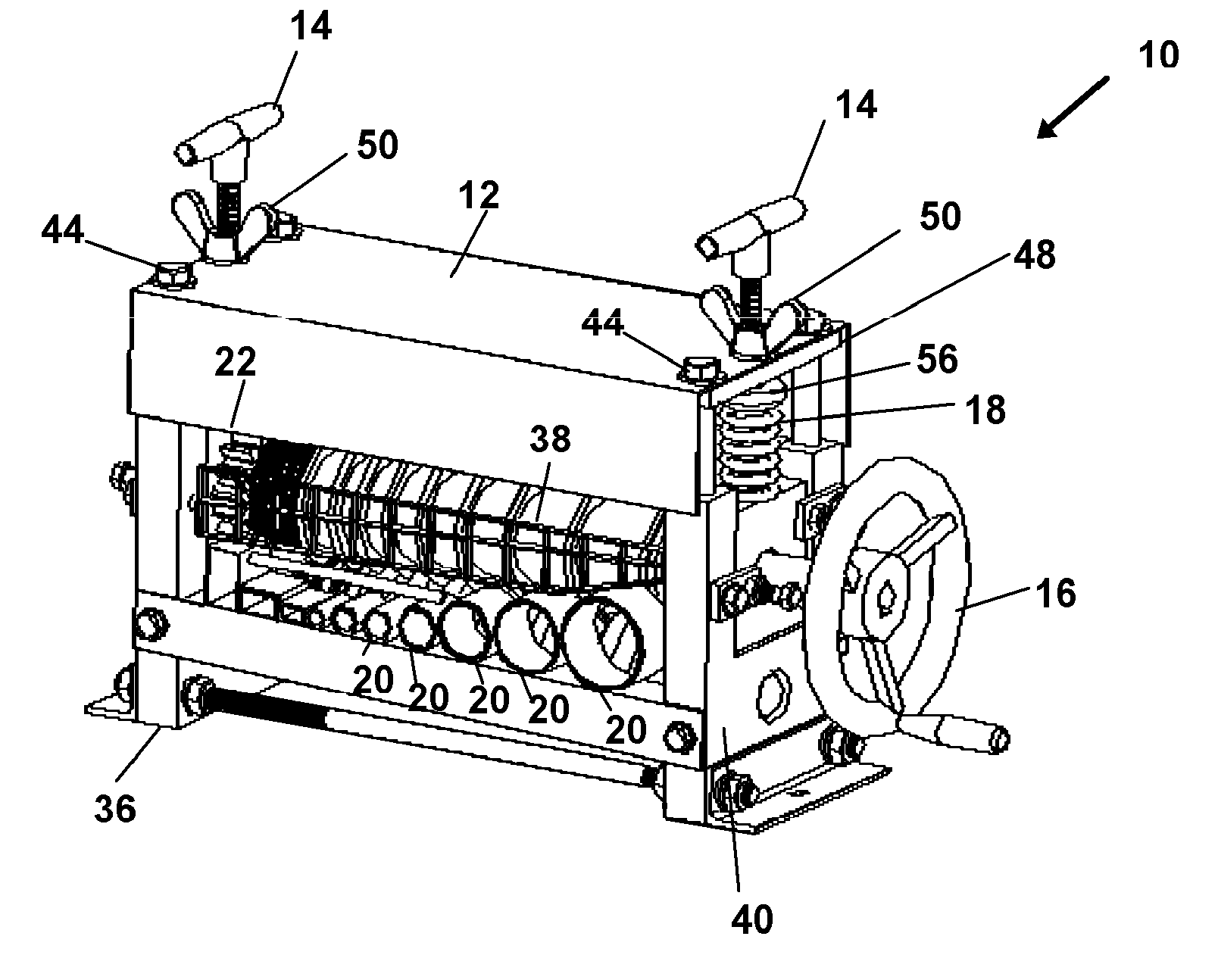
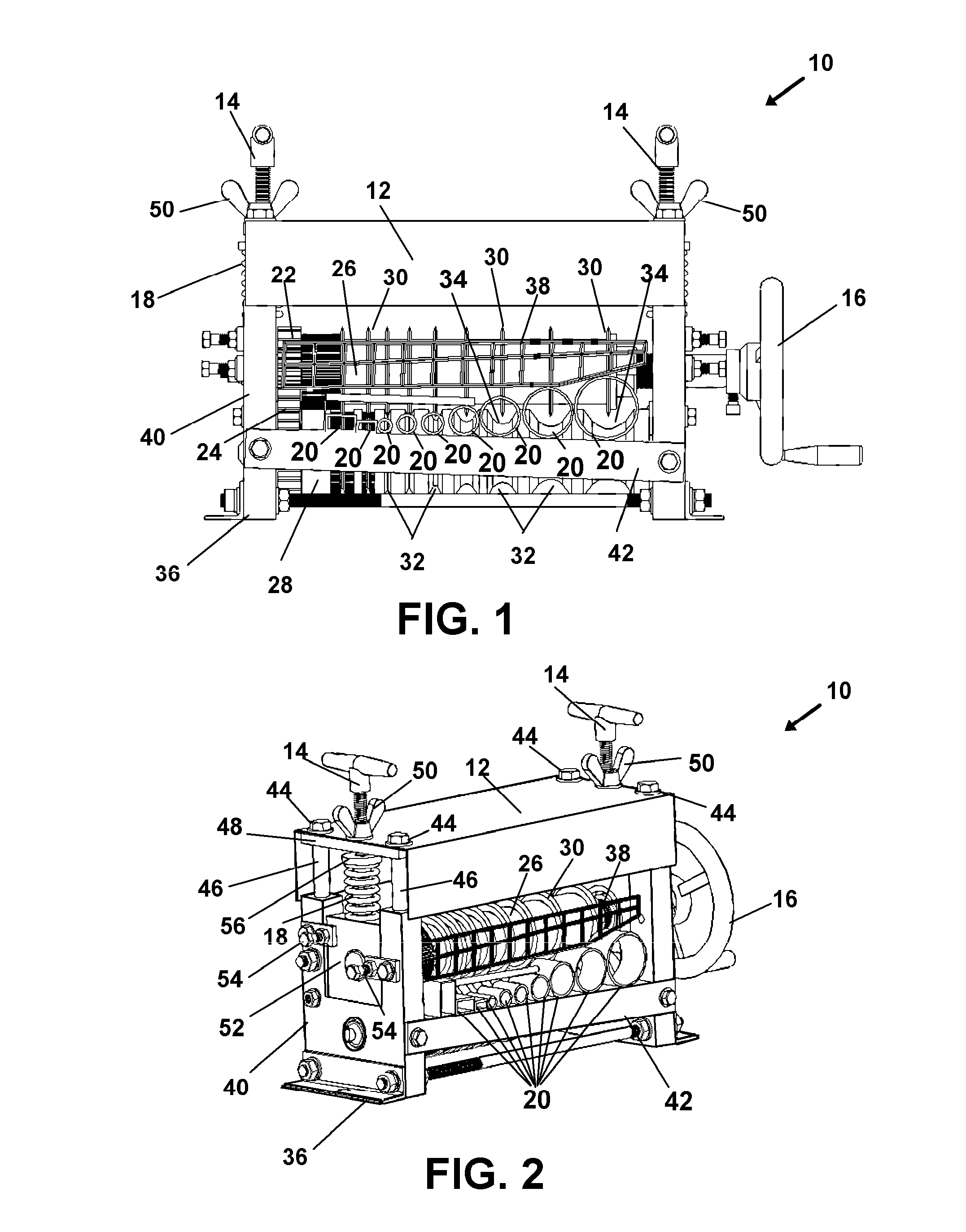
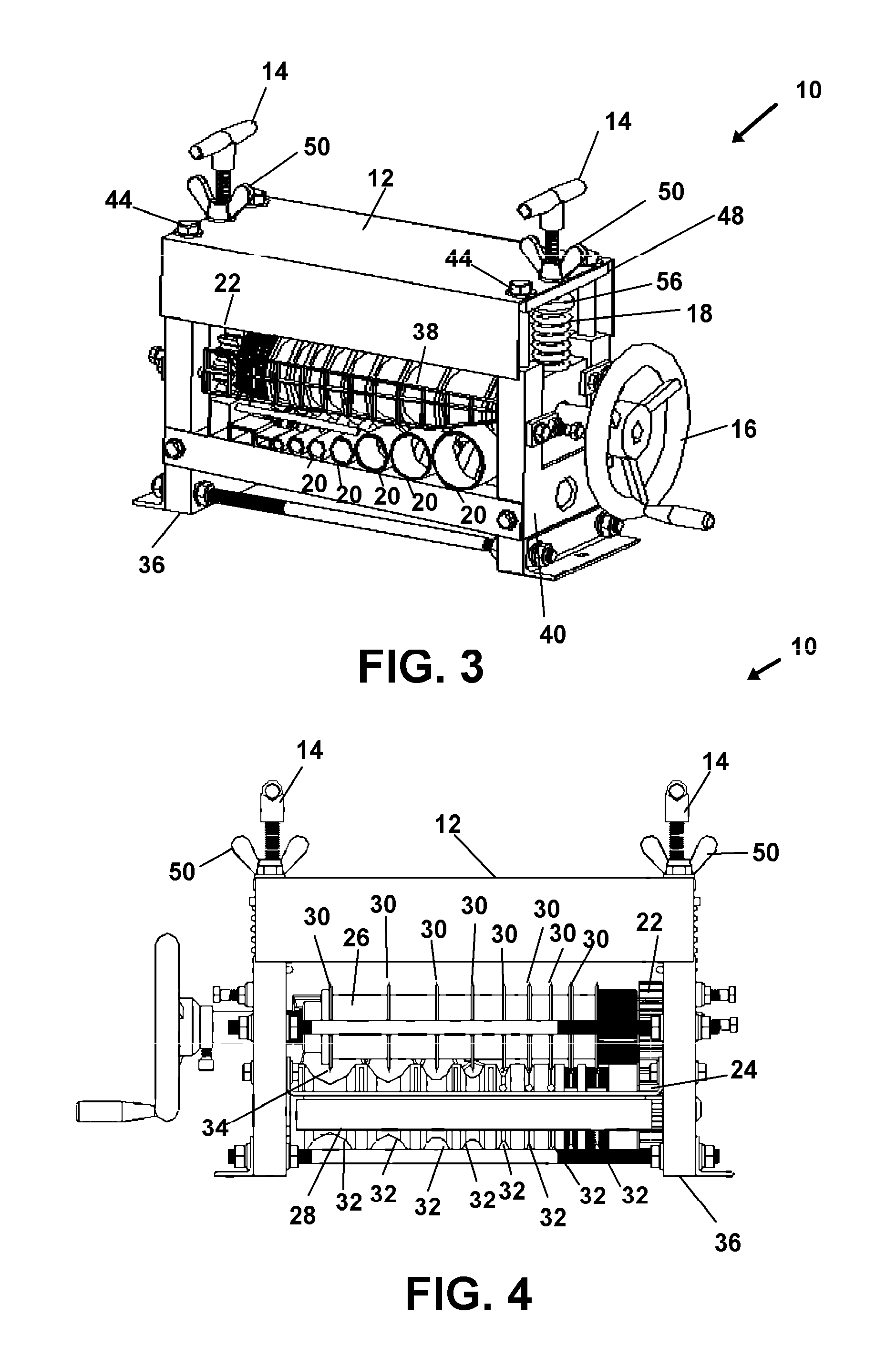
[0028]Now referring to drawings in FIGS. 1-6, wherein similar components are identified by like reference numerals, there is seen in FIG. 1-FIG. 4 views of the particularly preferred mode of the wire stripping device 10 intended to strip the jacket from electrical wire.

[0029]A shroud 12 forms the top of the frame 40 of the device 10 and serves as a protector and safety guard from the rotating or rolling knife blades 30 engaged with the first roller 26. Spring tensioning bolts 14 communicate through the shroud 12 and engage the bolt centering stop 56. The spring tensioning bolt 14 can be adjusted by rotating it in a direction to compress or lengthen the underlying spring 18 and thereby apply more or less tension to the spring 18 to impart more or less bias against the blades 30 toward the second roller 28 and through the insulation jacket 37 (FIG. 6) and against the side surface of an engaged wire core 35 side surface. This causes a compression of the wire core 35 and lower portion o...


PUM


Abstract

A device for removing an insulation jacket from a wire core of an insulated wire or cable is provided for encouraging recycling. The device employs cutting blades engaged to a first roller to cut a slice along the length of an inserted insulated wire or cable. A frictional engagement between the distal edge of the blade and an opposing recess surface provides for translation of the length of wire through the device during rotation of one or both of the blade and recess surface. Translational movement of the blades and a biasing force can enhance the frictional engagement and provide a distance of travel to prevent cutting of the insulated wire or cable.

Description

BACKGROUND OF THE INVENTION[0001]1. Field of the Invention[0002]This application claims priority to Chinese Application Serial Number 201030705094.5 filed on Dec. 31, 2011, and incorporated herein by reference in its entirety.[0003]The present invention relates to devices for stripping the insulating jacket from electrical wire. More specifically, the invention relates to a self adjusting wire stripping device for industrial employment, especially in recycling, wherein tensioned cutting blades are employed for cutting the insulating jacket from large amounts of wire being recycled and which automatically adjust to proper cutting for stripping as the elongated wire passes through it.[0004]2. Prior Art[0005]In order to protect the environment from over-use of raw materials, in the modern world many countries encourage recycling of prior-refined materials. In the case of products formed of metals from mining, such recycling saves huge amounts of energy required to mine the metal ore, a...

Claims


Application Information

Patent Timeline
Patent Type & Authority Applications(United States)
IPC IPC(8): H02G1/12
CPCH02G1/126H01B15/006Y02W30/82
Inventor NEWMAN, JERRY LEE
Owner THE NEWMAN TRADING COMPANY
Why Eureka
Try Eureka