Automotive HVAC Diffuser With Cooperating Wall Guide And Vane

a technology for hvac diffusers and automotive hvac systems, which is applied in ventilation systems, heating types, lighting and heating apparatuses, etc. it can solve the problems of less able to affect the air flow near the midline of the diffuser, the height of the interior vanes from the corresponding wall is restricted, and the flow is not uniform, so as to achieve uniform airflow and high flow. the effect of the region

Inactive Publication Date: 2012-07-05
AUTOMOTIVE COMPONENTS HOLDINGS
View PDF10 Cites 37 Cited by
  • Summary
  • Abstract
  • Description
  • Claims
  • Application Information

AI Technical Summary

Benefits of technology

[0008]The present invention overcomes limitations of the prior art by combining effects of a wall guide and a vane together to achieve uniform airflow across the evaporator core.
[0009]In one aspect of the invention, a case for an HVAC system in a transportation vehicle comprises at least two molded shells joined together along a parting line to receive a heat exchanger and a blower. The shells enclose a heat exchanger chamber, a blower chamber, and a diffuser section for guiding air from the blower chamber to the heat exchanger chamber. The diffuser section includes a floor, a ceiling, an outer wall, and an inner wall around a longitudinal axis between an inlet and an outlet. The walls provide an airflow path through the diffuser between the blower and heat exchanger chamber, and the airflow path makes a substantially right angle turn into the heat exchanger chamber which results in a tendency to create a high flow region at the outer wall because of centrifugal effects. The outer wall is shaped to form a wall guide partially projecting into the airflow path in the diffuser, wherein the wall guide has an upstream encroaching surface and a downstream retreating surface so that a portion of the guided air is directed from the outer wall toward the inner wall. At least one of the floor or the ceiling includes a vane projecting into and deflecting the guided air in the airflow path, wherein the vane has an upstream end proximate to the wall guide and a downstream end extending toward the heat exchanger chamber for initiating a portion of the substantially right angle turn for a portion of the airflow.

Problems solved by technology

Conventional blower / diffuser combinations produce a non-uniform flow that tends to produce high flows on the outer periphery of the diffuser due to centrifugal forces, and the high flow becomes concentrated at one end of the evaporator.
The height of interior vanes from a corresponding wall have been restricted due to limitations in the molding process and limitations associated with handling of the part after molding (e.g., breakage of the vanes).
Therefore, vanes can affect the air flow near to the diffuser walls but are less able to affect air flow near the midline of the diffuser.
Furthermore, the die draw of the molding process does not allow vanes to extend from walls that are perpendicular to one another (i.e., vanes cannot extend from both the curved outer peripheral wall and either of the transverse (i.e., floor and ceiling) walls in the same molded section).

Method used


Image

  • Automotive HVAC Diffuser With Cooperating Wall Guide And Vane
  • Automotive HVAC Diffuser With Cooperating Wall Guide And Vane
  • Automotive HVAC Diffuser With Cooperating Wall Guide And Vane

Examples


Embodiment Construction

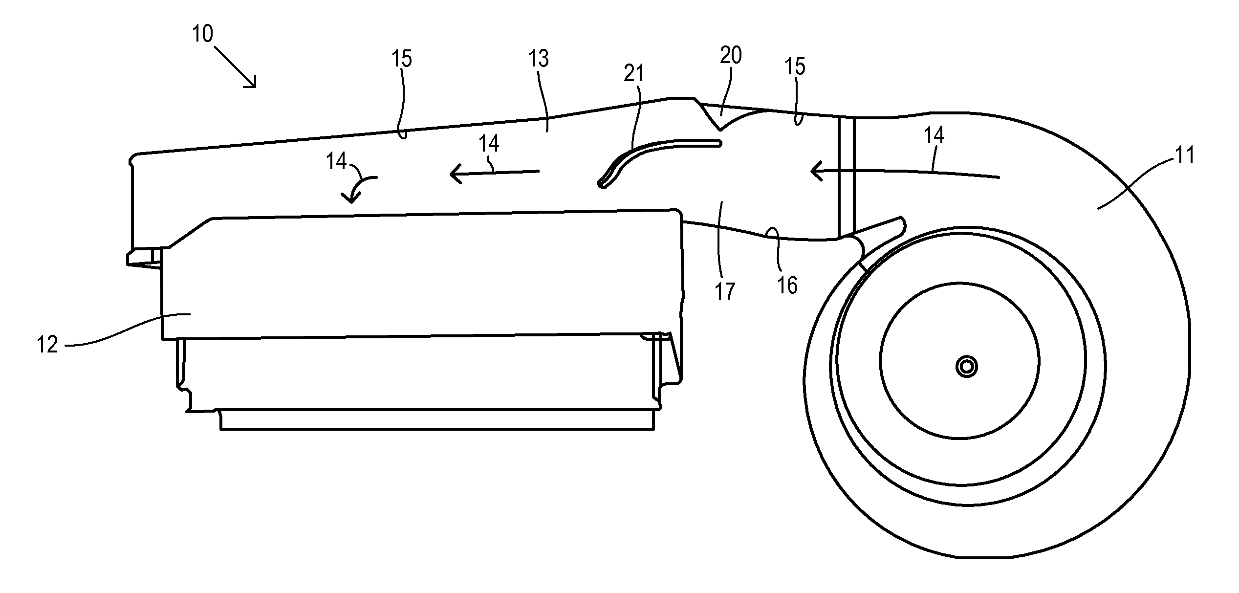
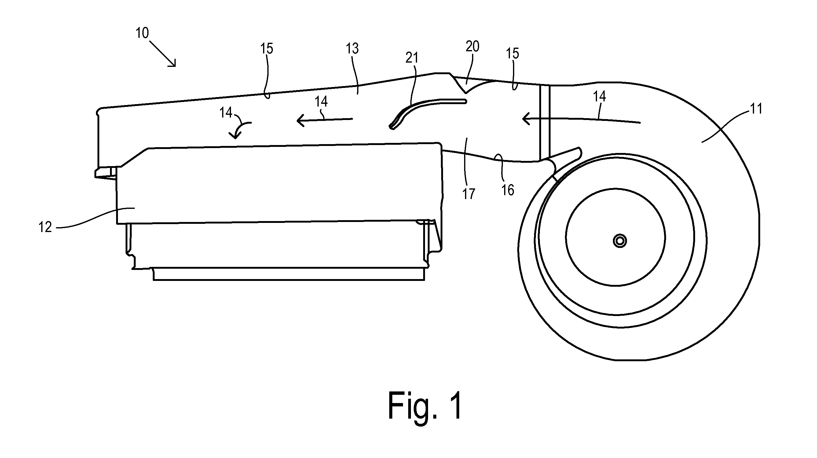
[0021]Referring now to FIG. 1, an HVAC case 10 includes a blower section 11, an evaporator section 12, and an intervening diffuser section 13. Blower section 11 receives a motor-driven bladed wheel (not shown) for created an air flow of fresh or recirculated air that is guided through diffuser section 13 to an evaporator core (not shown) mounted in evaporator section 12. Guided air 14 follows an airflow path and is required to make an approximately right angle turn in order to enter evaporator is section 12.

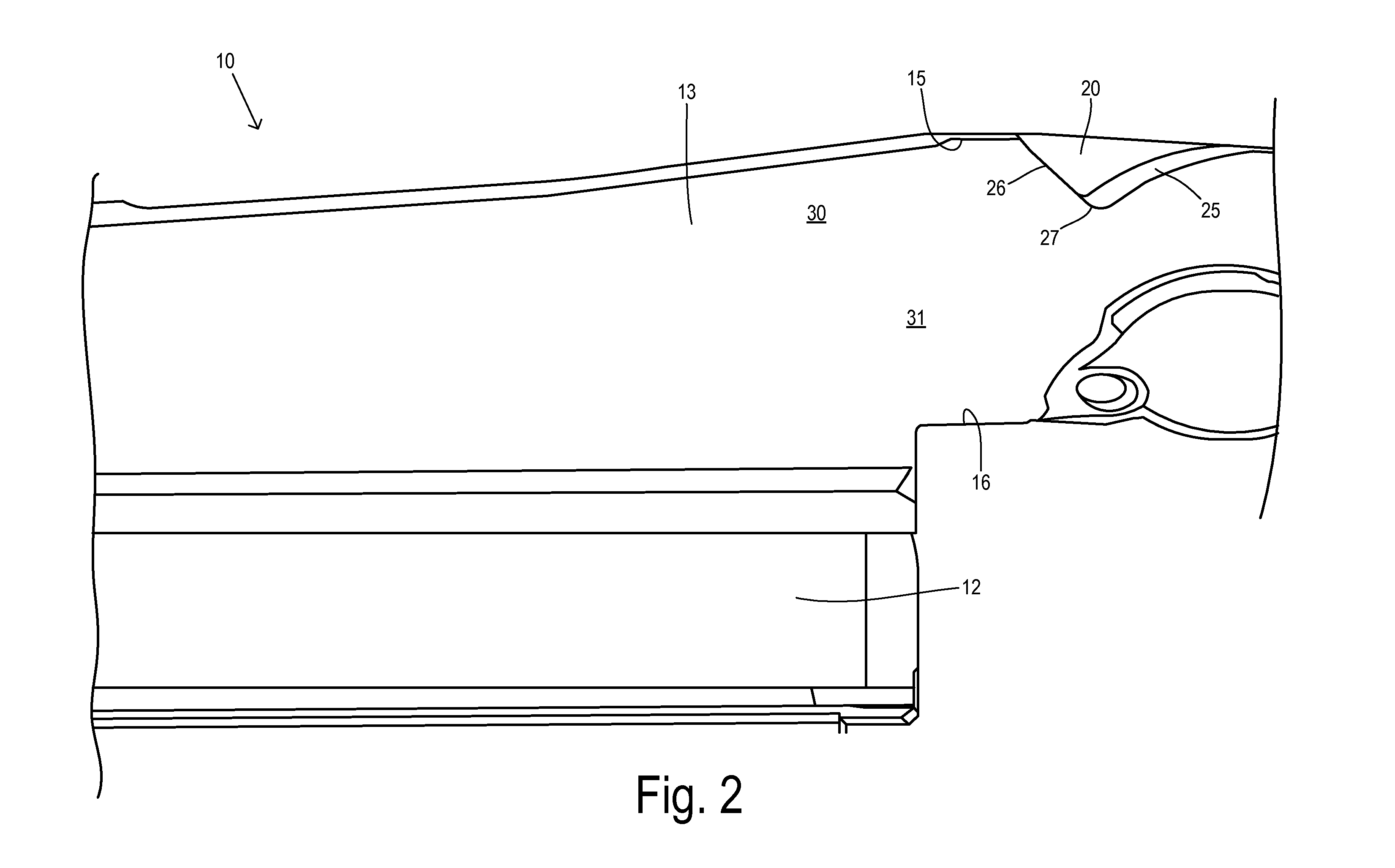
[0022]Diffuser section 13 includes an outer wall 15, an inner wall 16, a floor 17, and a ceiling (not shown) that surround a generally longitudinal axis of diffuser section 13 that extends between an inlet from the blower section 11 and an outlet to evaporator section 12. Due to centrifugal affects, a region of high flow is generally associated with outer wall 15 which results in non-uniform entry of the air flow into evaporator section 12. To improve uniformity and to reduce the...


PUM


Abstract

A case for an HVAC system has at least two molded shells joined together along a parting line to enclose a heat exchanger chamber, a blower chamber, and a diffuser section. The diffuser section includes a floor, a ceiling, an outer wall, and an inner wall around a longitudinal axis. The walls provide an airflow path through the diffuser between the blower and heat exchanger chamber, and the airflow path makes a substantially right angle turn into the heat exchanger chamber which results in a tendency to create a high flow region at the outer wall because of centrifugal effects. The outer wall is shaped to form a wall guide partially projecting into the airflow path in the diffuser, wherein the wall guide has an upstream encroaching surface and a downstream retreating surface so that a portion of the guided air is directed from the outer wall toward the inner wall. At least one of the floor or the ceiling includes a vane projecting into and deflecting the guided air in the airflow path, wherein the vane has an upstream end proximate to the wall guide and a downstream end extending toward the heat exchanger chamber for initiating a portion of the substantially right angle turn for a portion of the airflow.

Description

CROSS REFERENCE TO RELATED APPLICATIONS[0001]Not Applicable.STATEMENT REGARDING FEDERALLY SPONSORED RESEARCH[0002]Not Applicable.BACKGROUND OF THE INVENTION[0003]The present invention relates in general to a case for an automotive HVAC system, and, more specifically, to wall guide and vane features for improving air flow into an evaporator core.[0004]In a typical automotive HVAC system, a blower delivers fresh or recirculated air to heat exchangers (e.g., an evaporator) which is then distributed to the passenger cabin via ducts. A diffuser couples the air stream from the blower to the evaporator. Due to space requirements, the diffuser turns the air stream by about 90° for delivery to the evaporator. Conventional blower / diffuser combinations produce a non-uniform flow that tends to produce high flows on the outer periphery of the diffuser due to centrifugal forces, and the high flow becomes concentrated at one end of the evaporator.[0005]A uniform velocity distribution at the diffus...

Claims


Application Information

Patent Timeline
Patent Type & Authority Applications(United States)
IPC IPC(8): F24H9/02F24F7/007
CPCB60H1/00028B60H1/00514F24H9/0063F24F2013/088B60H2001/00092B60H2001/00721
Inventor JAIRAZBHOY, VIVEK A.SHAHABI, MEHRAN
Owner AUTOMOTIVE COMPONENTS HOLDINGS
Why Eureka
Try Eureka