Pre-landing, rotor-spin-up apparatus and method

a rotor spin-up and pre-landing technology, applied in the direction of rotorcraft, vehicles, aircrafts, etc., can solve the problems of disproportionate lift, reducing the lift generated by the advancing blade, and limiting the maximum flight speed of fixed-wing aircraft. , to achieve the effect of greater ability to stop

Active Publication Date: 2012-07-05
SKYWORKS GLOBAL INC
View PDF17 Cites 30 Cited by
  • Summary
  • Abstract
  • Description
  • Claims
  • Application Information

AI Technical Summary

Benefits of technology

[0039]With the greater amount of kinetic energy stored in the rotation of the rotor, a pilot may have a greater ability to stop the forward progress of the rotorcraft before touchdown. Accordingly, the rotorcraft may land with little to no forward roll (e.g., forward roll of one meter or less). Thus, the rotorcraft may execute a substantially vertical landing every time. This added capability provided by apparatus and methods in accordance with the present invention may support safe landings on smooth or rough terrain and at higher altitudes than previously available.
[0040]In selected embodiments, a rotorcraft in accordance with the present invention may be configured to support high speed flight (e.g., airspeeds of about 250 miles per hour and above). At such high advance ratios, autorotation is theoretically possible. However, the operating angle of attack of the rotor disk would have to be maintained w

Problems solved by technology

Although typical rotorcraft provide the significant advantage of vertical takeoff and landing (VTOL), they are much more limited in their maximum flight speed than are fixed-wing aircraft.
If left uncheck, this disproportionate lift may render the rotorcraft unflyable.
This, in turn, reduces the lift generated by the advancing blade.
This, in turn, increases the lift generated by the retreating blade.
However, lift equalization due to flapping is limited by retreating

Method used


Image

  • Pre-landing, rotor-spin-up apparatus and method
  • Pre-landing, rotor-spin-up apparatus and method
  • Pre-landing, rotor-spin-up apparatus and method

Examples


Embodiment Construction

[0060]It will be readily understood that the components of the present invention, as generally described and illustrated in the drawings herein, could be arranged and designed in a wide variety of different configurations. Thus, the following more detailed description of the embodiments of the system and method of the present invention, as represented in the drawings, is not intended to limit the scope of the invention, as claimed, but is merely representative of various embodiments of the invention. The illustrated embodiments of the invention will be best understood by reference to the drawings, wherein like parts are designated by like numerals throughout.

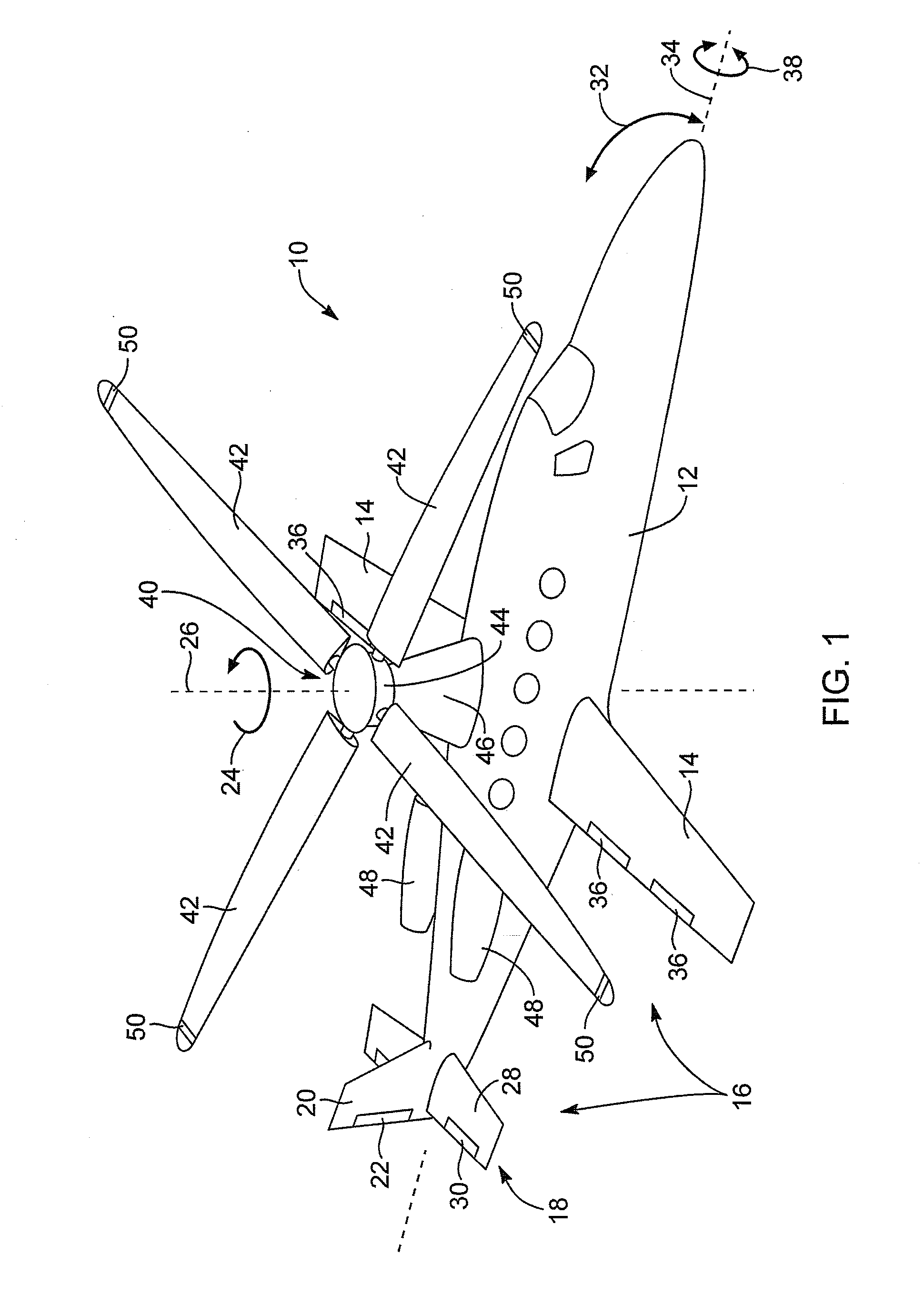
[0061]Referring to FIG. 1, a rotorcraft 10 in accordance with the present invention may include an airframe 12 defining a cabin for carrying an operator, passengers, cargo, or the like. The airframe 12 may include one or more fixed wings 14 or airfoils 14 providing lift to the rotorcraft 10. The wings 14 may be configured such t...


PUM


Abstract

A method and apparatus for reducing roll of rotorcraft landing in autorotation may include executing a flight with a rotorcraft. The flight may include first, second, and third portions ordered sequentially. During the first portion, the rotorcraft may be flown with the rotor exclusively in autorotation. During the second portion, the rotorcraft may be flown with the rotor powered at least partially by an engine of the rotorcraft, which may increase the rotational speed of the rotor. During the third portion, the rotorcraft may be flown with the rotor exclusively in autorotation. The flight and the third portion may terminate simultaneously with a touch down of the rotorcraft. Kinetic energy stored in the rotor during the second portion, during the third portion, bring the ground speed of the rotorcraft to substantially zero before touching down.

Description

RELATED APPLICATIONS[0001]This application claims the benefit of co-pending U.S. patent application Ser. No. 13 / 199,671, filed on Sep. 7, 2011, which claims the benefit of U.S. Provisional Patent Application Ser. No. 61 / 381,291, filed on Sep. 9, 2010, co-pending U.S. patent application Ser. No. 13 / 199,684, filed on Sep. 7, 2011, which claims the benefit of U.S. Provisional Patent Application Ser. No. 61 / 403,099, filed on Sep. 9, 2010, co-pending U.S. patent application Ser. No. 13 / 199,678, filed on Sep. 7, 2011, which claims the benefit of U.S. Provisional Patent Application Ser. No. 61 / 403,097, filed on Sep. 9, 2010, co-pending U.S. patent application Ser. No. 13 / 199,682, filed on Sep. 7, 2011, which claims the benefit of U.S. Provisional Patent Application Ser. No. 61 / 381,313, filed on Sep. 9, 2010, co-pending U.S. patent application Ser. No. 13 / 199,681, filed on Sep. 7, 2011, which claims the benefit of U.S. Provisional Patent Application Ser. No. 61 / 403,111, filed on Sep. 9, 201...

Claims


Application Information

Patent Timeline
IPC IPC(8): B64C27/08B64C27/12
CPCB64C27/025B64C27/26B64C27/18B64C2027/8272B64C27/82B64C27/027
Inventor SONNEBORN, WALTER GERD OSKAR
Owner SKYWORKS GLOBAL INC
Why Eureka
Try Eureka