Device for optical imaging, tracking, and position measurement with a scanning MEMS mirror

a scanning mems mirror and optical imaging technology, applied in the direction of optical radiation measurement, navigation instruments, instruments for comonautical navigation, etc., can solve the problems of insufficient precision and flexibility, system does not solve the problem of object searching/selecting, and lack of depth (z-axis) measurements,

Active Publication Date: 2012-07-05
MIRRORCLE TECH
View PDF4 Cites 68 Cited by
  • Summary
  • Abstract
  • Description
  • Claims
  • Application Information

AI Technical Summary

Benefits of technology

[0011]The objective of the work that led to embodiments of the present invention was to develop and demonstrate an optical-MEMS based, very low cost and versatile platform for tracking and position measurement in a variety of situations. The platform could also be used in bar-code scanning, LIDAR, biomedical imaging, and other types of imaging and 3D scanning applications. Use of MEMS mirrors with the potential to use wide-angle lenses provides the possibility of tracking and imaging in a very large volume, and very far distances (e.g. use of remote-control IR source-detector modules can provide a range of 50 m or more). At the same time the technology provides low-cost production, high speed, small size, and very low power consumption.

Problems solved by technology

However a simple and low cost solution that can provide enough precision and flexibility has not been available.
Recent proliferation of low-cost inertial sensors has not addressed the problem of position tracking.
Cassinelli et al demonstrated a scanning mirror-based tracking solution [3-4]; however their system does not solve the problem of object searching / selecting and does not have adequate depth (Z-axis) measurements.
Unfortunately, many existing tracking systems tend to lose resolution when the object is close in.
Unfortunately, the image is two-dimensional and additional information is usually needed in order to derive three-dimensional position information.
In addition, a CCD typically has a limited field of view.
Furthermore, there is a large cost differential associated with increasing the resolution of CCD array.
The small size of the scanning unit could result in lower cost, faster scanning, and portable implementations, but it creates a problem for the system designer in that the small mirror aperture receives a very tiny portion of the reflected light, perhaps too low for most applications.

Method used


Image

  • Device for optical imaging, tracking, and position measurement with a scanning MEMS mirror
  • Device for optical imaging, tracking, and position measurement with a scanning MEMS mirror
  • Device for optical imaging, tracking, and position measurement with a scanning MEMS mirror

Examples


Embodiment Construction

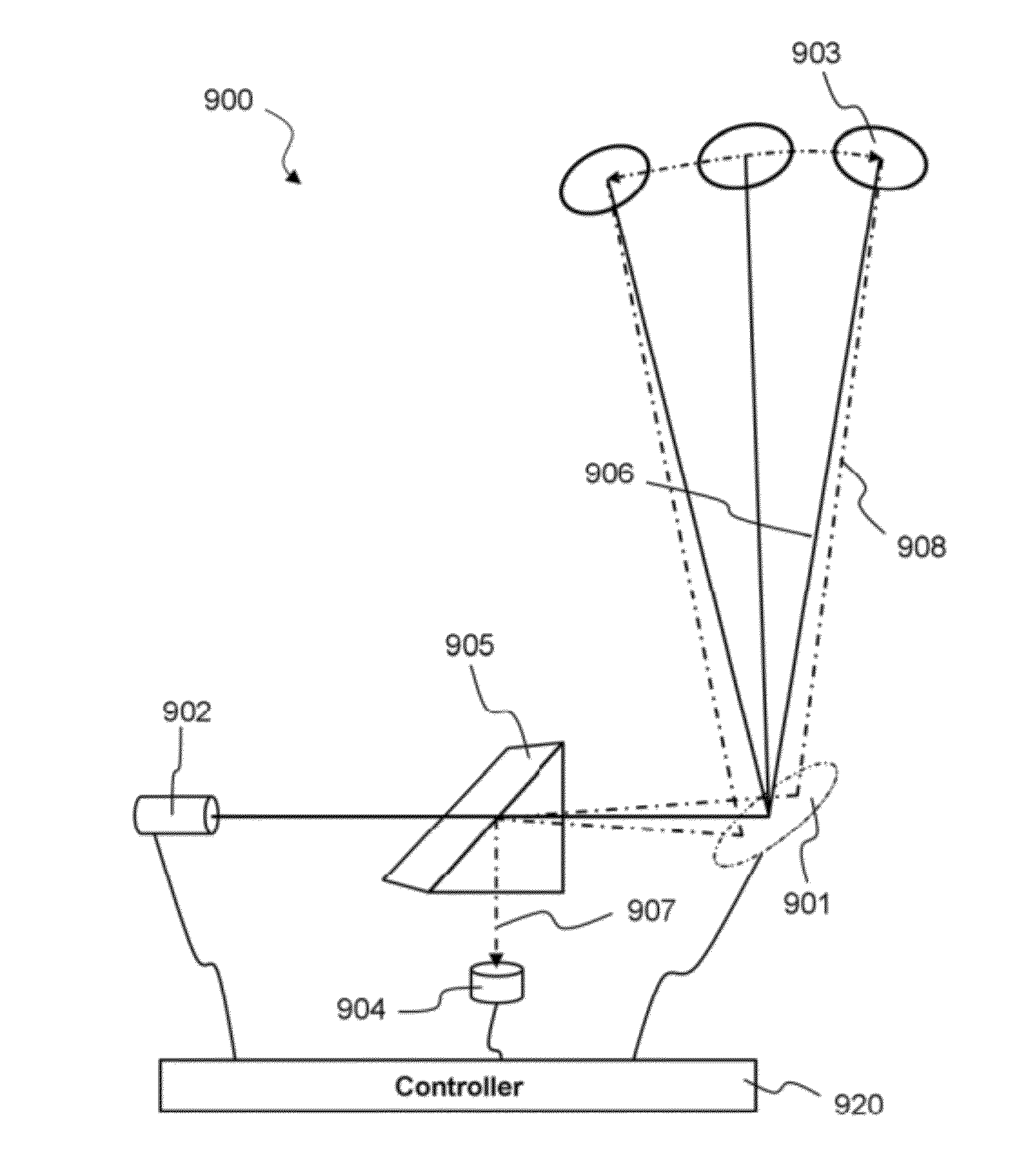
[0056]According to an embodiment of the present invention a system may be created that may be e.g. attached to a personal computer, to allow a computer to continuously monitor the 3D position of an object. The object may be held in the hand of a human user and moved about by hand in an arbitrary manner. In addition, the computer may take derivatives of the position measurement and thus obtain velocity and acceleration data of that object in 3D space. The object being waved by the user may include a retro reflector or may be one or multiple retro reflectors. In other embodiments the object may be an optical source.

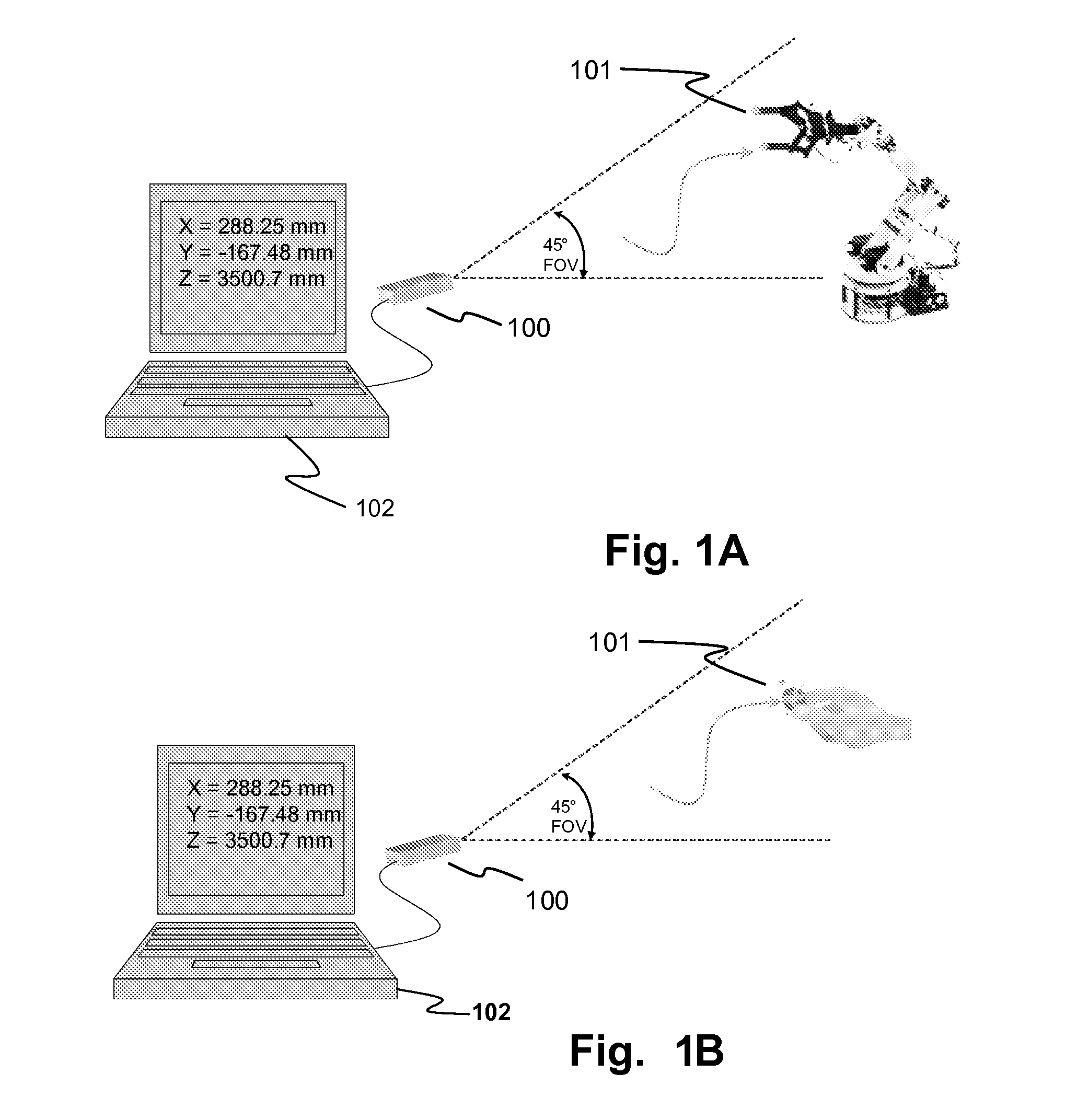
[0057]Applications exist where a light source and a photo detector are used to scan objects, such as a barcode scanner, flatbed scanner, biomedical imaging and microscopy, OCT-type 3D imaging, 3D scanning and digitization of objects, and some applications of LiDAR. In the case of a barcode scanner, the light source is scanned across a barcode, and the light reflected back o...


PUM


Abstract

An optical tracking system can include at least one scanning detector having a scanning mirror and one or more fixed photo-detectors located near the scanning mirror. The scanning mirror can be configured to deflect a light beam from a source towards a retroreflective target and the photodetectors are configured to collect a portion of the light beam that is retroreflected from the target. A scanning optical detector apparatus may optionally comprise a substrate, a scanning mirror having at least one portion monolithically integrated into the substrate, and one or more photodetectors monolithically incorporated into the substrate. It is emphasized that this abstract is provided to comply with rules requiring an abstract that will allow a searcher or other reader to quickly ascertain the subject matter of the technical disclosure. It is submitted with the understanding that it will not be used to interpret or limit the claims' scope or meaning.

Description

CLAIM OF PRIORITY[0001]This application claims the priority benefit of U.S. Provisional Patent Application No. 61 / 434,652 filed Jan. 20, 2011, the contents of which are incorporated herein by reference.[0002]This application is a continuation of and claims the priority benefit of U.S. patent application Ser. No. 12 / 538,093, filed Aug. 7, 2009 (now U.S. Pat. No. 7,924,441), which was co-pending with U.S. Provisional Patent Application 61 / 434,652. U.S. patent application Ser. No. 12,538,093 is a non-provisional of U.S. Provisional Patent Application No. 61 / 087,604, filed Aug. 8, 2008, the entire contents of which are incorporated herein by reference.[0003]This application is a non-provisional of and claims the priority benefit of U.S. Provisional Patent Application No. 61 / 087,604.CROSS-REFERENCE TO RELATED APPLICATIONS[0004]This application is related to U.S. Pat. No. 7,295,726, US Patent Application Publication number 20080061026, U.S. patent application Ser. No. 11 / 465,835 (now U.S....

Claims


Application Information

Patent Timeline
Patent Type & Authority Applications(United States)
IPC IPC(8): G01C21/20G01C21/00
CPCG01B11/002
Inventor MILANOVIC, VELJKO
Owner MIRRORCLE TECH
Why Eureka
Try Eureka