
Apparatus and method for obtaining maximum value and minimum value in plurality of digital input signals

Inactive Publication Date: 2012-07-05
ELECTRONICS & TELECOMM RES INST
View PDF3 Cites 0 Cited by
  • Summary
  • Abstract
  • Description
  • Claims
  • Application Information

AI Technical Summary

Benefits of technology

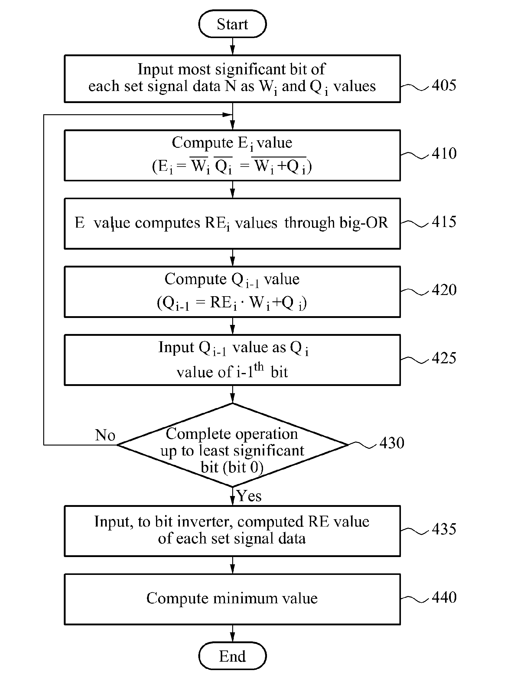
[0010]An aspect of the present invention provides an apparatus and method that may resolve a complexity of performing a calculation through several stages when a relatively large number of populations is involved in obtaining a maximum value or a minimum value, and may obtain a result after a predetermined time delay irrespective of an increasing number of populations.
[0020]According to an embodiment of the present invention, it is possible to perform a fast process by easing a delay, in a digital circuit, for obtaining a minimum / maximum value from a plurality of input signals.

Problems solved by technology

When a calculation is performed through several stages, a relatively long period of time may be expended, which may be inappropriate for a high-speed circuit design.

Method used


Image

  • Apparatus and method for obtaining maximum value and minimum value in plurality of digital input signals
  • Apparatus and method for obtaining maximum value and minimum value in plurality of digital input signals
  • Apparatus and method for obtaining maximum value and minimum value in plurality of digital input signals

Examples


Embodiment Construction

[0027]Reference will now be made in detail to exemplary embodiments of the present invention, examples of which are illustrated in the accompanying drawings, wherein like reference numerals refer to the like elements throughout. Exemplary embodiments are described below to explain the present invention by referring to the figures.

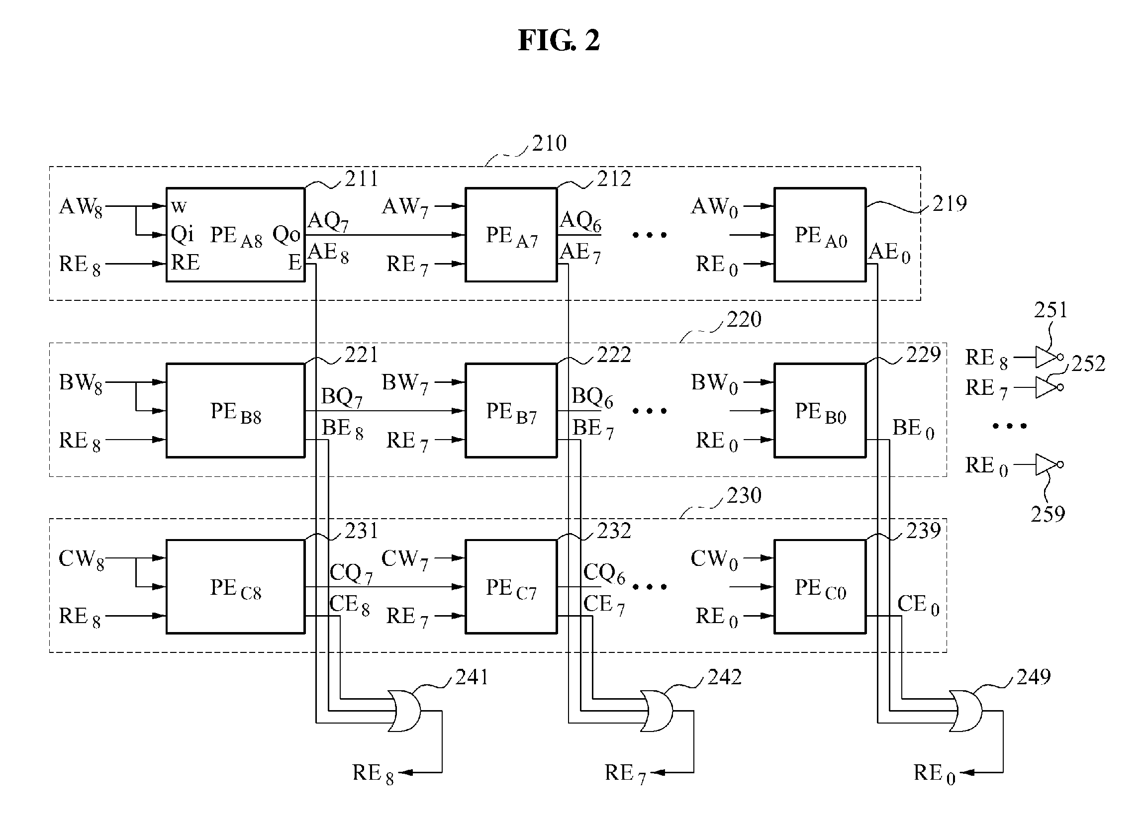
[0028]FIG. 2 is a diagram illustrating a configuration of operation blocks for obtaining a maximum value or a minimum value in a plurality of digital signals according to embodiments of the present invention.

[0029]A configuration of operation blocks for obtaining a minimum value according to embodiments of the present invention may include N×W bit processing elements in which a set signal has N pieces of data, each of which includes W bits, W OR gates, and W inverters.

[0030]Referring to FIG. 2, the set signal may correspond to three pieces of data A, B, and C, and each of the three pieces of data may include nine bits, that is, (A: AW8, . . . , AW0), (B: BW...


PUM


Abstract

The present invention relates to a digital signal processing circuit, and more particularly, to a method and apparatus for generating a maximum value or a minimum value used for designing the digital signal processing circuit. An apparatus for obtaining a maximum value or a minimum value from N digital input signals may include N×W bit processing elements to receive an input of W bits of each of the N digital input signals, W OR operators to receive an input of N operation values output from bit processing elements, and to perform an OR operation, respectively, and W inverters to invert an output value for each of the W OR operators.

Description

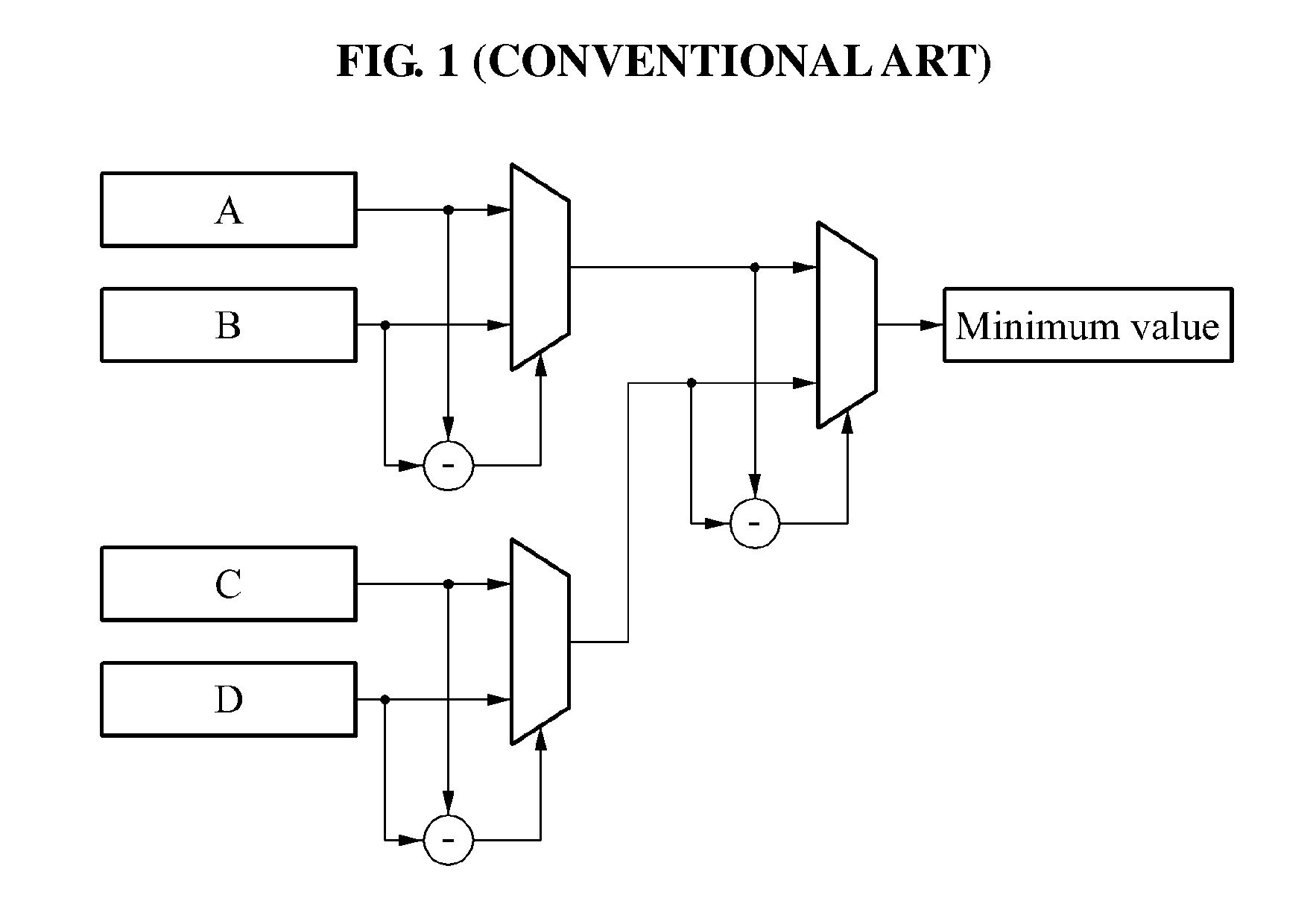
CROSS-REFERENCE TO RELATED APPLICATION[0001]This application claims the benefit of Korean Patent Application No. 10-2010-0138518, filed on Dec. 30, 2010, in the Korean Intellectual Property Office, the disclosure of which is incorporated herein by reference.BACKGROUND[0002]1. Field of the Invention[0003]The present invention relates to a digital signal processing circuit, and more particularly, to a method and apparatus for generating a maximum value or a minimum value used for designing the digital signal processing circuit.[0004]2. Description of the Related Art[0005]A conventional scheme for obtaining a maximum value or a minimum value in a digital system may obtain the maximum value or the minimum value between two values by subtracting one from another. The conventional scheme may determine a sign of a subtracted value to output the maximum value or the minimum value between the two values.[0006]FIG. 1 is a diagram illustrating a configuration of a circuit for obtaining a minim...

Claims


Application Information

Patent Timeline
IPC IPC(8): H03K19/20
CPCH03K19/23
Inventor CHOI, SUNG WOOLEE, WOO YONGCHUNG
Owner ELECTRONICS & TELECOMM RES INST
Learn More