
Device for controlling optical frequency, method of manufacturing such a device

Inactive Publication Date: 2012-07-05
CENT NAT DE LA RECHERCHE SCI
View PDF6 Cites 12 Cited by
  • Summary
  • Abstract
  • Description
  • Claims
  • Application Information

AI Technical Summary

Benefits of technology

[0015]The addition according to the invention of this material with nonlinear optical properties makes it possible to create a very high nonlinear interaction between the two eigen optical frequencies F1 and F2 of the cavity existing from the association of the cavity with the photonic crystal, this interaction being all the more reinforced as each frequency is associated to a resonant eigen mode. It is thus made possible to parameter the direct coupling between the resonant modes associated to the association of the cavity and the photonic crystal, such as either to create photons making it possible to accomplish modes F1 and F2, or to absorb photons at frequency F2 in order to emit photons at frequency F1 (if F2 is higher than F1), or to emit photons at frequency F1−F2 or F1+F2 based on photons with frequencies F1 and F2.
[0042]Thus, a device for controlling optical frequency around a central working frequency, exhibiting the advantages of the device object of the present invention, is achieved. Amongst others, the device obtained by this manufacturing method has the advantage of being compact, to very highly couple and in a nonlinear manner the two optical eigen frequencies generated, as well as to allow for a parameterization of this coupling, ensuring a continuous control of the two frequencies.

Problems solved by technology

Nevertheless, the drawback of such a device resides in the impossibility of continually controlling the two frequencies F1 and F2 of the generated optical resonant modes.

Method used


Image

  • Device for controlling optical frequency, method of manufacturing such a device
  • Device for controlling optical frequency, method of manufacturing such a device
  • Device for controlling optical frequency, method of manufacturing such a device

Examples


first embodiment

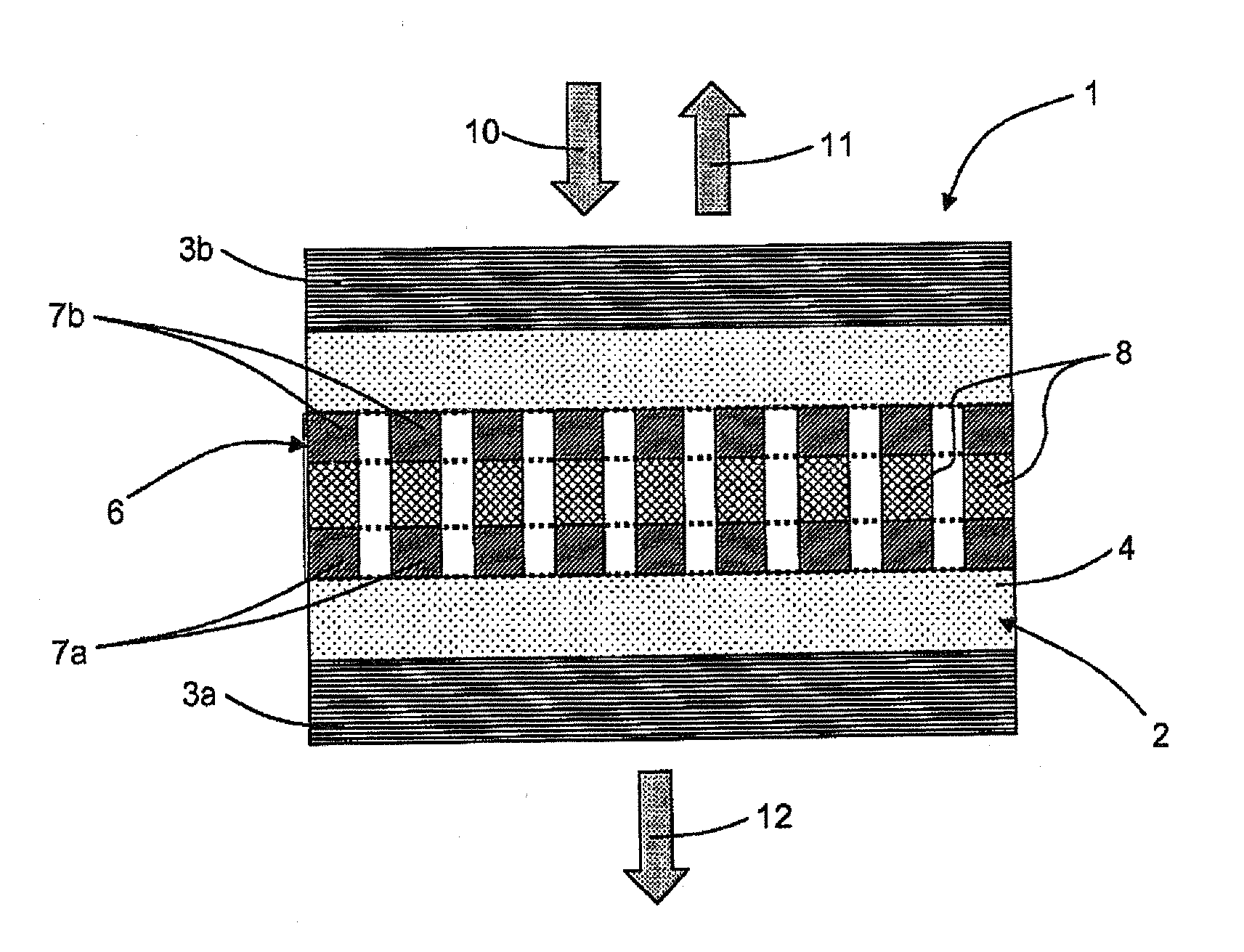
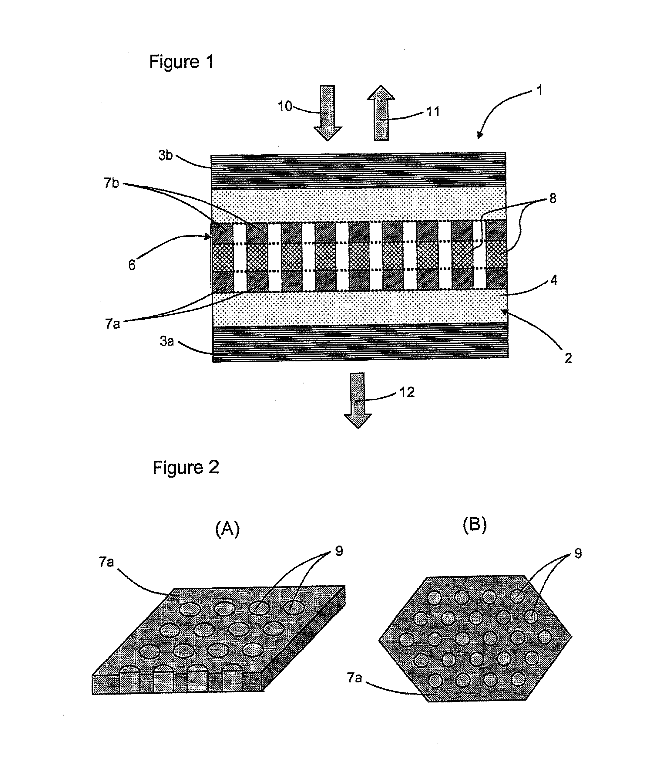
[0053]With reference to FIG. 1, a device 1 for controlling optical frequency according to the invention comprises two coupled resonant members: a vertical cavity 2 and a photonic crystal membrane 6. This device associates these two members 2 and 6, which are liable to act individually as optical resonators. It operates around a central working frequency F0, to which corresponds a working wavelength λ0, by generating two eigen optical frequencies whereof the values are located symmetrically on either side of the central optical frequency F0.

[0054]The vertical cavity 2 is a Fabry-Pérot type cavity. It comprises two Bragg mirrors 3a and 3b. These mirrors are parallel and constitute partially reflecting walls whereof the reflection coefficients are higher than 95%. They are constituted in one succession of high index layers (silicon—Si) and low index layers (silicon dioxide—SiO2). Between these two walls, the cavity 2 comprises a medium 4, constituted for example in silicon dioxide (SiO...

second embodiment

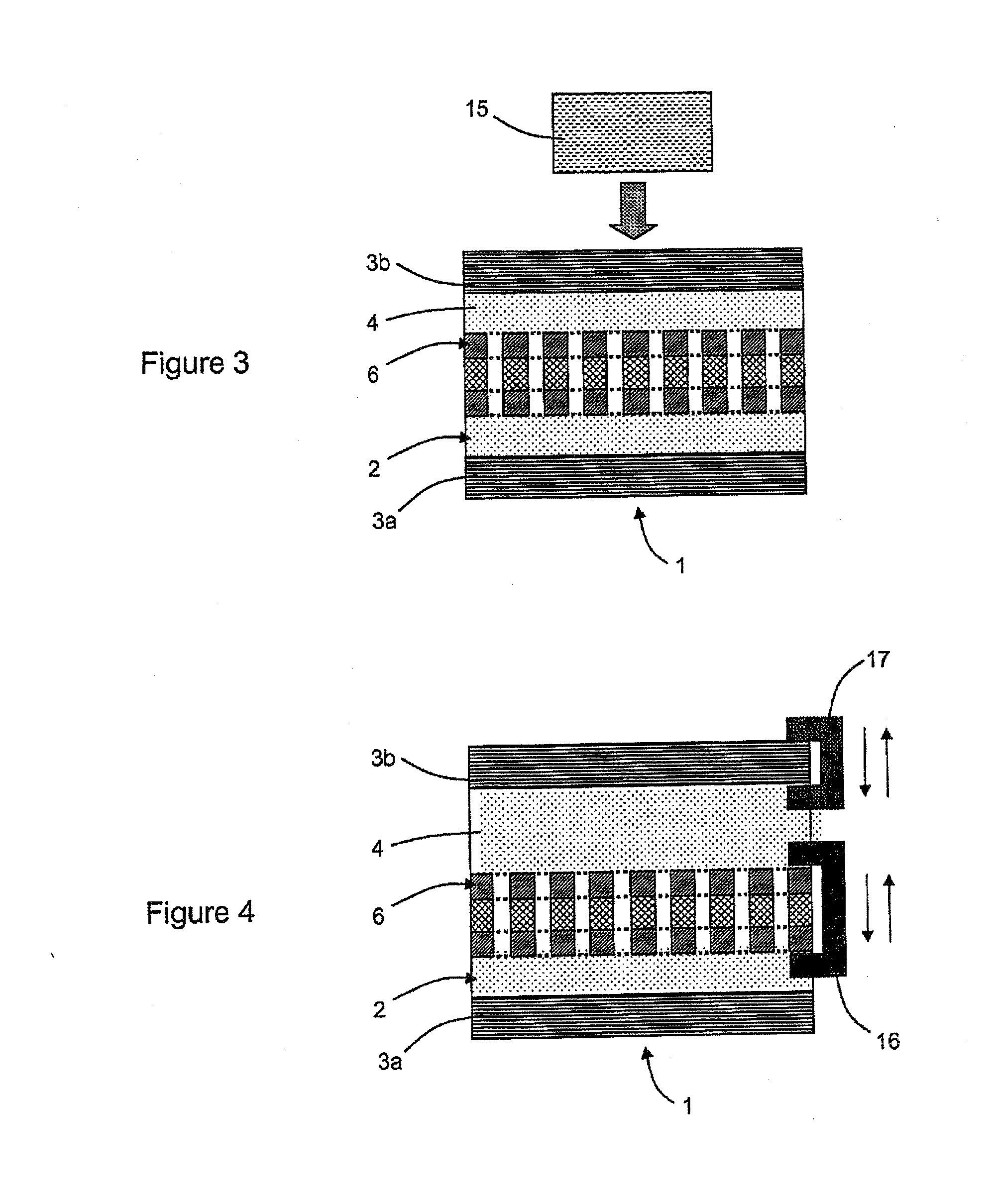
[0067] the medium 4 comprised between the two walls 3a and 3b of the cavity 2 is a laser effect medium. The device 1 receives optical information transported respectively at frequencies F1 and F2, whereof the modulation frequencies are identical. The active medium is capable of absorbing at the two frequencies F1 and F2. The optical pumping means 15 are arranged such that only the power at frequency F2 makes it possible to ensure the absorption saturation. When the laser threshold is reached, the structure converts the received power at frequency F2 into a coherent signal at frequency F1.

third embodiment

[0068] the nonlinear optical properties of the material constituting the layer of photonic crystal of the membrane 6 are of the order of 2. The device 1 receives optical information transported respectively at frequencies F1 and F2, whereof the modulation frequencies are identical. The active medium is capable of absorbing at the two frequencies F1 and F2. The optical pumping means 15 are arranged such that the power at frequency F1 or the power at frequency F2 interchangeably makes it possible to ensure the absorption saturation. Hence, signals of frequency F1+F2 and F2−F1 may be generated. The high confinement of two eigen optical resonant modes in a same place at frequencies F1 and F2 makes it possible to reinforce the efficiency of the optical frequency conversion.

[0069]Examples of embodiments of the invention for wavelength tuning are illustrated by FIG. 4. To this end, the device comprises means 16 for vertically moving the membrane 6 and means 17 for relatively vertically mov...


PUM

PropertyMeasurementUnit
Frequencyaaaaaaaaaa
Wavelengthaaaaaaaaaa
Reflection coefficientaaaaaaaaaa

Abstract

The present invention relates to a device for controlling optical frequency (F1, F2) about a central working frequency (F0). This device comprises a vertical cavity (2) formed of two parallel and partially reflecting walls (3a, 3b), and a membrane (6) comprising at least one layer (7a, 7b) structured in the form of a photonic crystal. In this device, the two walls (3a, 3b) are separated by an optical distance substantially proportional to half the wavelength (λ0) corresponding to the central working frequency (F0). The membrane (6) is integrated between the walls (3a, 3b) of the cavity (2) and devised in such a way as to exhibit a mode of optical resonance at this central working wavelength (λ0). At least one layer of the device is made up of at least one portion of a material exhibiting nonlinear optical properties. The present invention also relates to various systems implementing means of optical pumping and such a device for controlling optical frequency, as well as to a method of manufacturing such a device for controlling optical frequency.

Description

TECHNICAL FIELD OF THE INVENTION[0001]The present invention relates to the field of optical frequency control, particularly for the conversion of optical frequency into terahertz, as well as for their tuning. This control occurs by trapping the photons in a small volume—whereof the dimensions have for order of magnitude the wavelength—during a monitored period and by controlling the spatial distribution of the optical modes as well as their interaction with the outside world.[0002]The invention more particularly relates to a device for controlling optical frequency around a central working frequency, comprising a vertical cavity formed of two parallel and partially reflecting walls, and a membrane comprising at least one layer structured in the form of a photonic crystal.[0003]It also relates to a method for manufacturing such a device.PRIOR ART[0004]The prior art in this field comprises resonators achieved according to a so-called 2.5 dimensional approach, as disclosed in the paten...

Claims


Application Information

Patent Timeline
IPC IPC(8): G02F1/35B32B37/14
CPCB82Y20/00G02B1/005G02F1/01716G02F1/3534H01S5/183G02F2201/346G02F2203/15H01S5/105G02F2/004H01S5/11
Inventor LETARTRE, XAVIERVIKTOROVITCH, PIERRELECLERCQ, JEAN-LOUISSEASSAL, CHRISTIAN
Owner CENT NAT DE LA RECHERCHE SCI
Learn More