Micro-speaker

a microphone and microphone technology, applied in the field of transducers, can solve the problem that the voice coil cannot vibrate with sufficient amplitude without extra space provided

Inactive Publication Date: 2012-07-05
AAC ACOUSTIC TECH (SHENZHEN) CO LTD
View PDF5 Cites 12 Cited by
  • Summary
  • Abstract
  • Description
  • Claims
  • Application Information

AI Technical Summary

Problems solved by technology

However, as mentioned above, as the micro-spacer is designed smaller and thinner,

Method used


Image

  • Micro-speaker
  • Micro-speaker
  • Micro-speaker

Examples


Embodiment Construction

[0010]Reference will now be made to describe an exemplary embodiment of the present disclosure in detail.

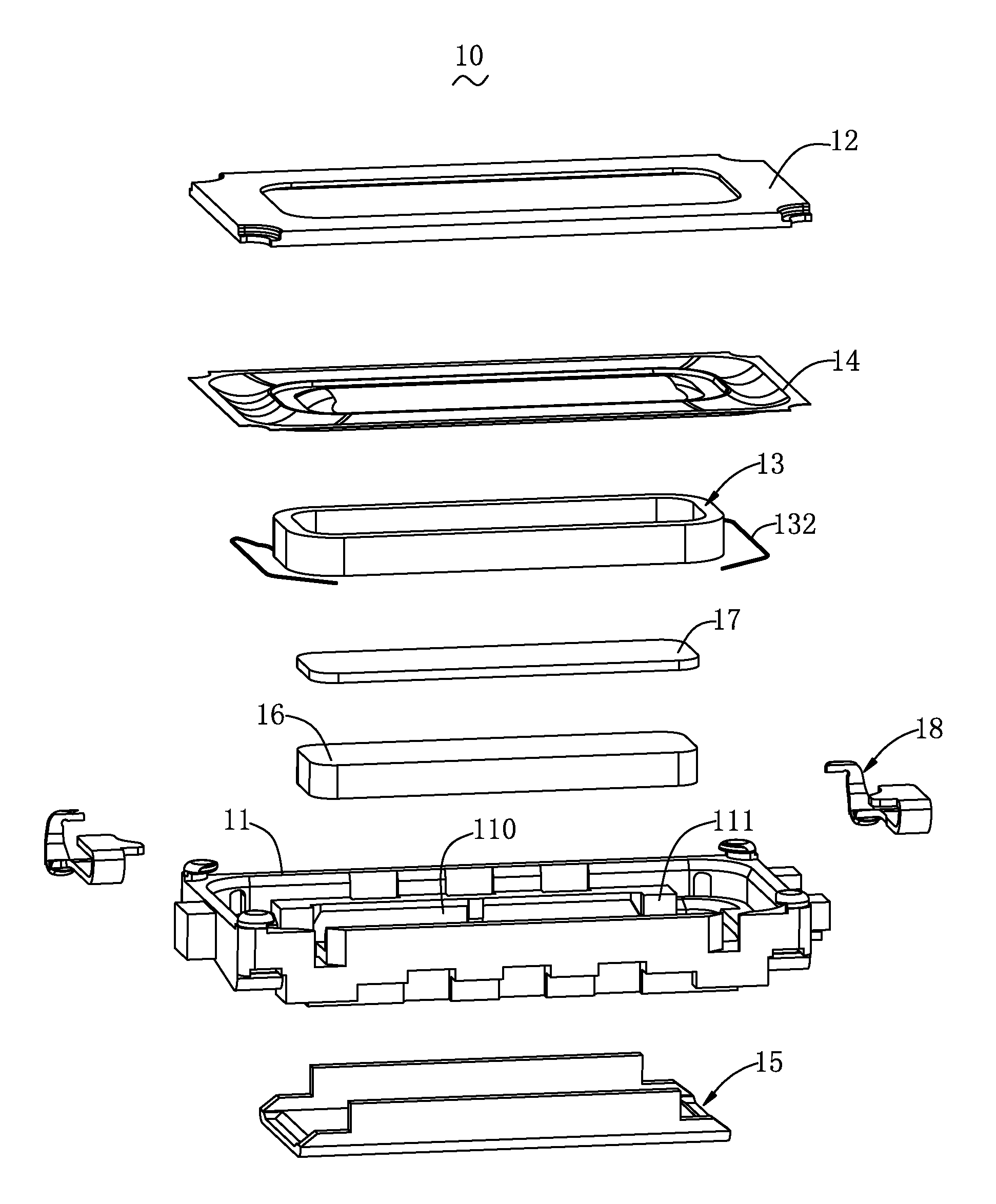
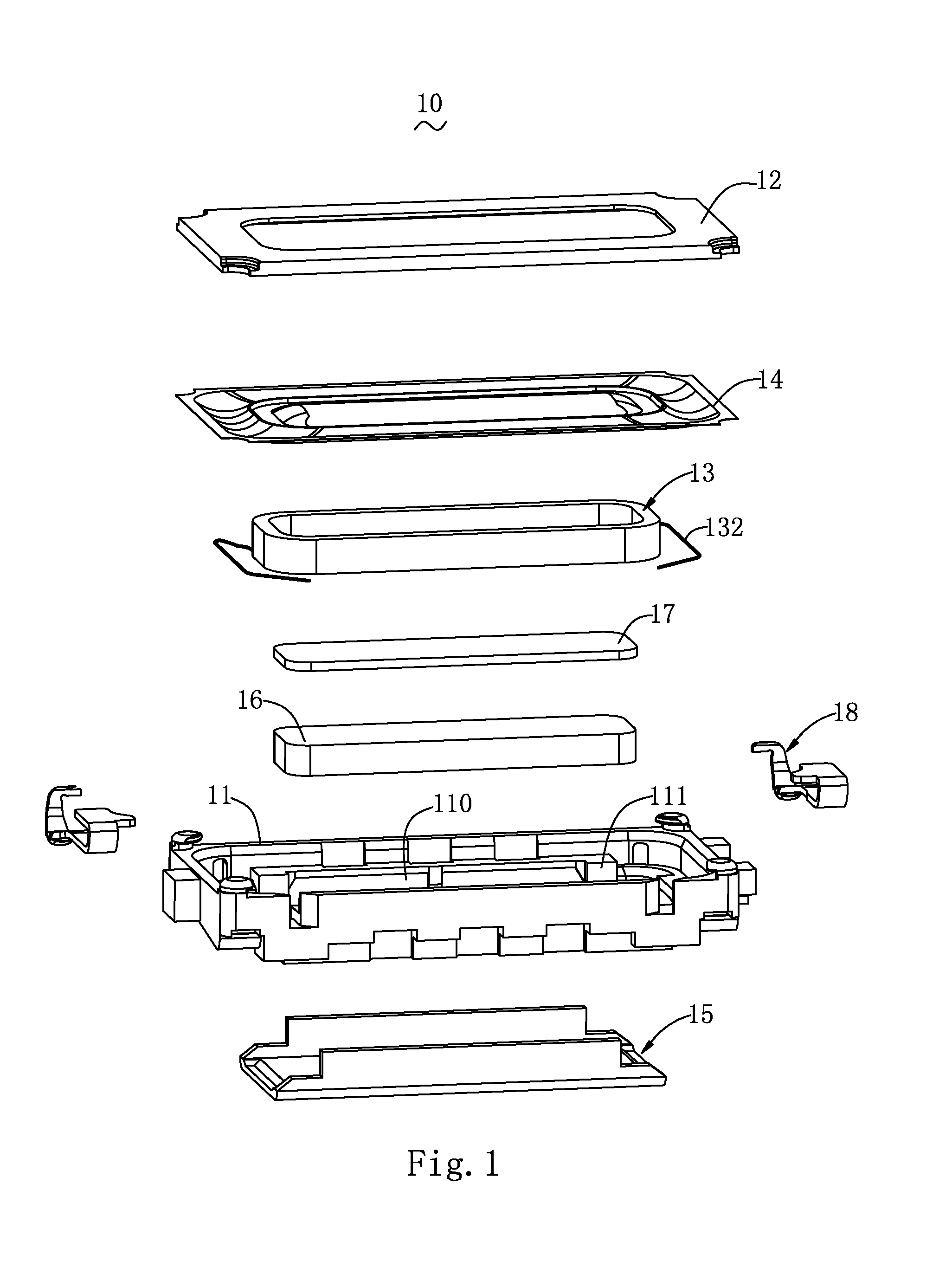
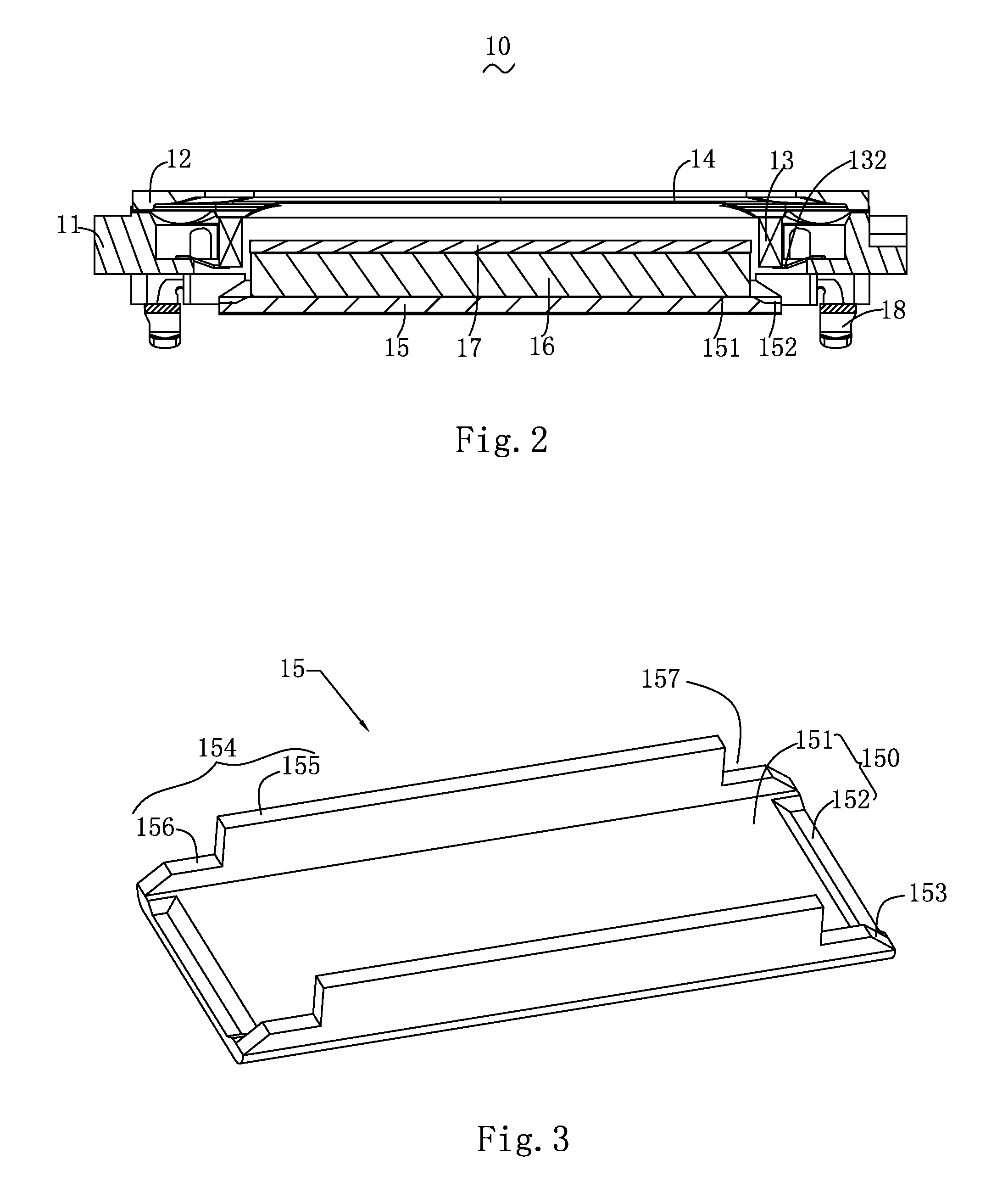
[0011]Referring to FIGS. 1-2, a micro-speaker 10 comprises a frame 11 forming a hollow space 110, a diaphragm 14 attached to the frame 11, a cover 12 covering the diaphragm 14 and attached to the frame 11, a yoke 15 engaged with the frame 11, a magnet 16 received in the yoke 15, a pole plate 17 attached on the magnet 16, and a voice coil 13 activating the diaphragm 14. Further, a pair of conductive terminals 18 is provided in the frame electrically connected to a leads 132 of the voice coils 13. Thus, the voice coils 13 can receive electrical signals via the conductive terminals 18. A magnetic gap is formed between the yoke 15 and the magnet 16. In addition, the frame 11 further defines a plurality of positioning portions 111 extending from inner sidewalls thereof.

[0012]The frame 11, cooperatively with the cover 12, defines a chamber therebetween for receiving the yoke 15, the ma...


PUM


Abstract

A micro-speaker is disclosed. The micro-speaker includes a frame defining a hollow space, a diaphragm attached to the frame, a voice coil positioned on the diaphragm, a cover covering the diaphragm and attached to the frame forming a housing, a yoke received in the hollow space and attached to the frame, a magnet received in the yoke, and a pole plate attached on the magnet. The yoke includes a bottom wall, and two ends of the base wall are provided with a groove corresponding to the magnetic gap, respectively. A width of the groove is greater than that of the thickness of the voice coil.

Description

FIELD OF THE INVENTION[0001]The present disclosure relates to transducers to be mounted in terminal equipments for converting electrical signals to audible sounds, and more particularly to a micro-speaker.DESCRIPTION OF RELATED ART[0002]Sound which can be heard by a person's auditory sense is transmitted in the form of waves. The sound having the wave form moves air molecules and vibrates the tympanic membrane, thus allowing a person to hear the sound. In order to provide audible sounds, various kinds of speakers have been developed. The speaker is generally coupled to audio equipment or an amplifier for use as a large sound producing means for considerably amplifying volume. Alternatively, the speaker may be used as a small sound producing means having small size and volume.[0003]As such, the small-sized speaker may be mounted to a small electronic product, such as a mobile phone, a PDA, or a notebook computer. As the wireless age begins, consumers want to consume various contents ...

Claims


Application Information

Patent Timeline
IPC IPC(8): H04R1/02
CPCH04R9/02H04R9/04H04R2400/11H04R2499/11H04R9/025H04R9/06
Inventor MENG, YI-MING
Owner AAC ACOUSTIC TECH (SHENZHEN) CO LTD
Why Eureka
Try Eureka