Fluid pump

a technology of fluid pump and actuator, which is applied in the direction of machines/engines, liquid fuel engines, positive displacement liquid engines, etc., can solve the problems of increasing the size of the entire fluid pump, reducing the capacity (flow rate and pressure), and reducing the size of the piezoelectric pump, so as to improve the pumping capacity, reduce the loss caused by bending vibration of the actuator, and increase the flow rate.

Active Publication Date: 2012-07-05
MURATA MFG CO LTD
View PDF2 Cites 57 Cited by
  • Summary
  • Abstract
  • Description
  • Claims
  • Application Information

AI Technical Summary

Benefits of technology

[0016]With this structure, the pressure and the flow rate that can be generated, i.e., pumping capabilities, can be significantly improved. The reason for this may be as follows. Because of the provision of the cover plate unit, the generation of a pressure wave or a synthetic jet flow around at least one center vent of the planar section caused by vibration of the actuator and the thin sheet portion of the planar section is prevented and suppressed.
[0017]One or a plurality of peripheral vents may be provided at a peripheral portion of the actuator facing area. With this arrangement, a positive pressure produced in the peripheral portion of the actuator facing area can be utilized, thereby making it possible to perform suction/discharge in the same plane.
[0018]The actuator may be retained by an elastic structure such that a certain gap is provided between the actuator and the planar section. With this arrangement, the gap between the actuator and the planar section ...

Problems solved by technology

However, electronic devices into which such a piezoelectric pump is integrated are becoming smaller, and accordingly, it is also desirable to reduce the size of a piezoelectric pump without decreasing the capabilities (flow rate and pressure) of the pump.
Accordingly, when using a piezoelectric pump having a structure of the related art, there are limitati...

Method used


Image

  • Fluid pump
  • Fluid pump
  • Fluid pump

Examples


first preferred embodiment

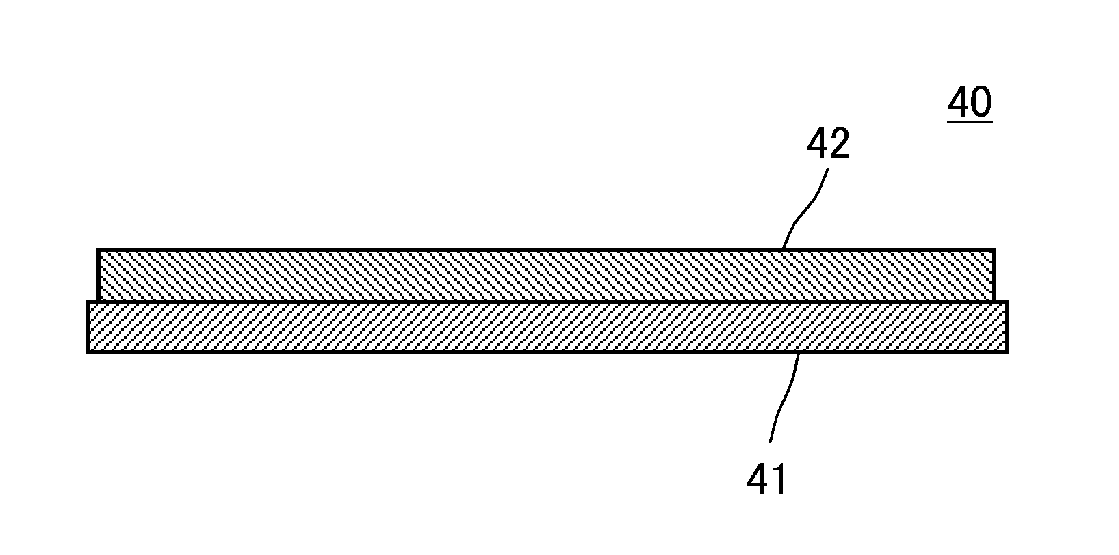
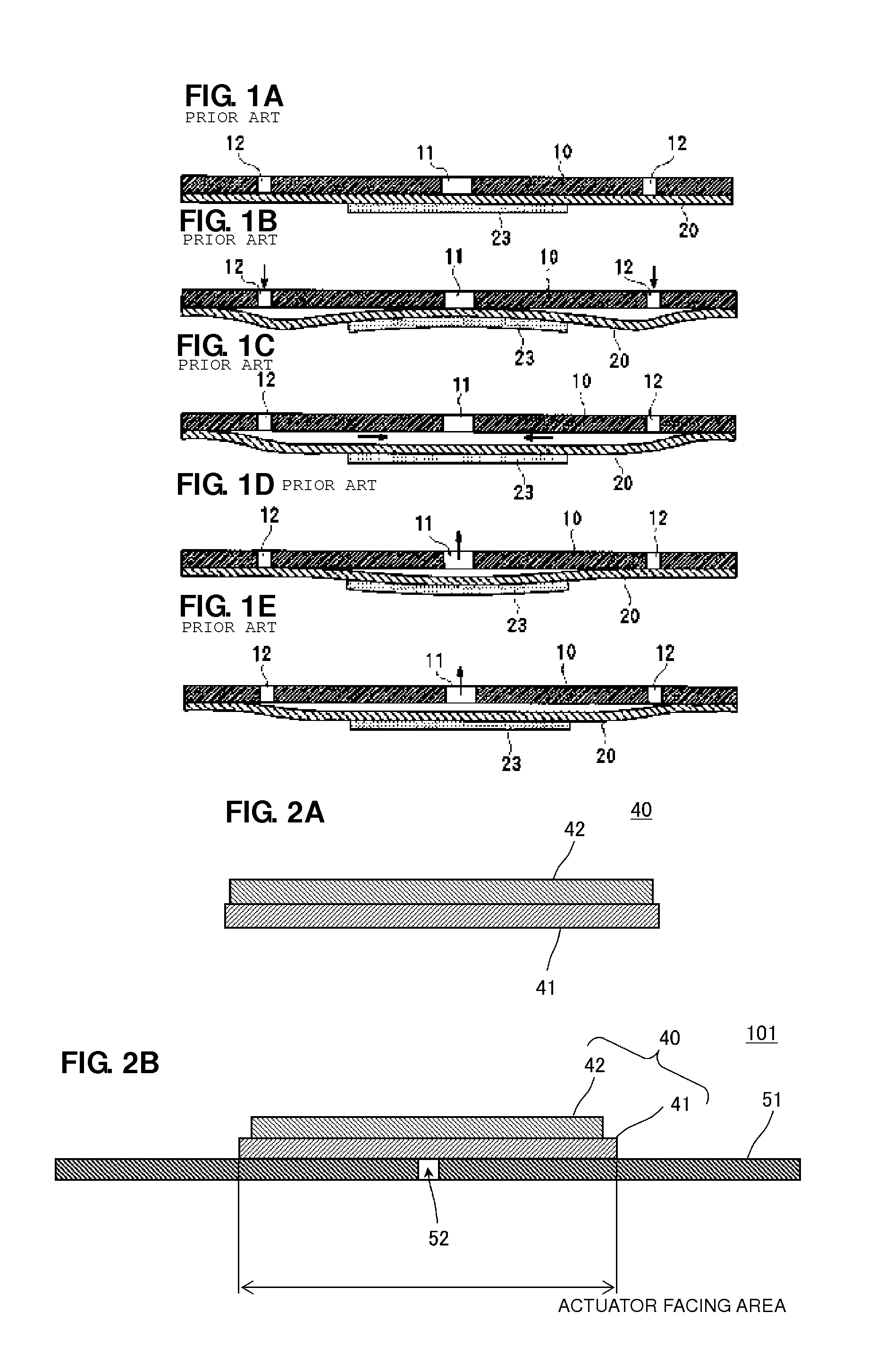
[0044]FIG. 2A is a sectional view illustrating the center of an actuator 40 provided in a fluid pump according to a first preferred embodiment. FIG. 2B is a sectional view illustrating the major portion of a fluid pump 101 in the non-driving state according to the first preferred embodiment. The actuator 40 is preferably formed by attaching a disk-shaped piezoelectric element 42 to a disk-shaped diaphragm 41. The diaphragm 41 is preferably made of metal, such as stainless steel or phosphor bronze, for example. An electrode film is arranged over almost the entirety of each of the top and bottom surfaces of the piezoelectric element 42. The electrode disposed on the bottom surface of the piezoelectric element 42 is electrically connected to or capacitively coupled to the diaphragm 41. A conductor wire is connected to the electrode located on the top surface of the piezoelectric element 42, and a drive circuit is electrically connected to this conductor wire and the diaphragm 41. Then,...

second preferred embodiment

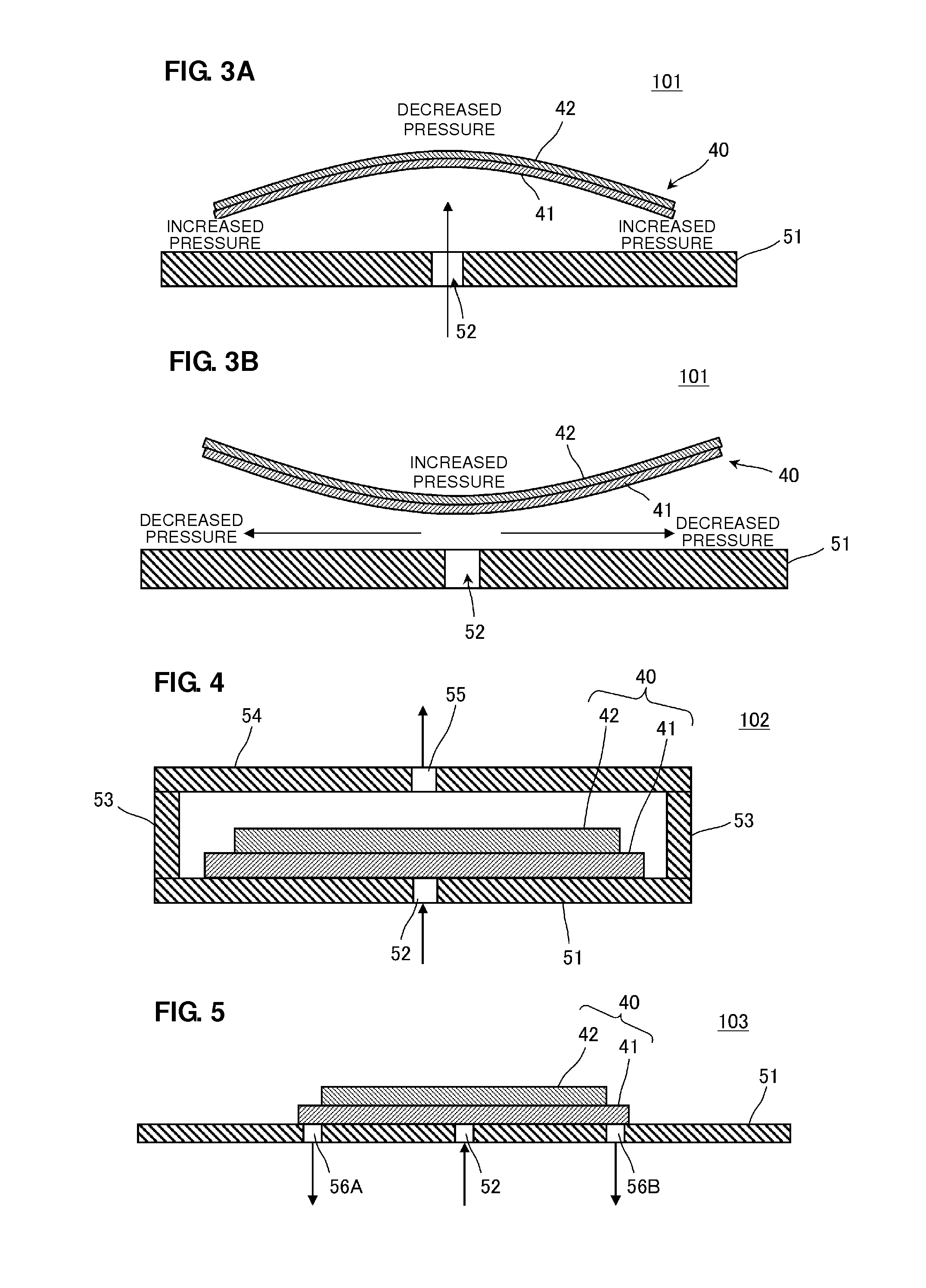
[0056]FIG. 4 is a sectional view illustrating the major portion of a fluid pump 102 in a non-driving state according to a second preferred embodiment. The fluid pump 102 includes an actuator 40 and a planar section 51. In the actuator 40, a disk-shaped piezoelectric element 42 is attached to a disk-shaped diaphragm 41. On the top of the planar section 51, a spacer 53 and a lid 54 are provided to surround the periphery of the actuator 40. A discharge vent 55 is preferably provided in the lid 54. The actuator 40 is similar to that of the first preferred embodiment, and the peripheral portion thereof is not restrained by the planar section 51. Only when the fluid pump 102 is not driven is the actuator 40 placed opposite the planar section 51 such that it is in contact with the planar section 51.

[0057]When the actuator 40 performs a bending vibration, a fluid is sucked through a center vent 52 in accordance with the principle described in the first preferred embodiment. The sucked fluid...

third preferred embodiment

[0058]FIG. 5 is a sectional view illustrating the major portion of a fluid pump 103 according to a third preferred embodiment. The fluid pump 103 includes an actuator 40 and a planar section 51 preferably made of a metal plate, such as stainless steel or phosphor bronze, for example. The peripheral portion of the actuator 40 is not restrained by the planar section 51.

[0059]Only when the fluid pump 103 is not driven is the actuator 40 placed opposite the planar section 51 such that it is in contact with the planar section 51. A center vent 52 is preferably provided at or in an area adjacent to the center of an area of the planar section 51 that faces the actuator 40 (actuator facing area). A plurality of peripheral vents 56A, 56B, etc. are also preferably provided at the peripheral portion of the actuator facing area.

[0060]Concerning the pressure of the gaps in the actuator facing area, both the pressure of the central portion and the pressure of the peripheral portion momentarily ch...


PUM


Abstract

A small-sized, low-profile fluid pump having high pumping capabilities includes an actuator and a planar section including a metal plate. The actuator includes a disk-shaped piezoelectric element attached to a disk-shaped diaphragm. As a result of application of a square-wave or sine-wave drive voltage, the actuator performs a bending vibration from the central portion to the peripheral portion. The peripheral portion of the actuator is not restrained. The actuator performs a bending vibration in the state in which it is in proximity to the planar section while facing the planar section. A center vent is provided at or in an area adjacent to the center of an actuator facing area of the planar section that faces the actuator.

Description

BACKGROUND OF THE INVENTION[0001]1. Field of the Invention[0002]The present invention relates to a fluid pump suitable for moving a fluid, such as air or liquid.[0003]2. Description of the Related Art[0004]A piezoelectric pump of the related art is disclosed in International Publication No. 2008 / 069264. FIGS. 1A-1E illustrate a pumping operation of the piezoelectric pump disclosed in International Publication No. 2008 / 069264 in a third-order resonance mode. The piezoelectric pump includes a pump body 10, a diaphragm 20 having an outer peripheral portion thereof fixed to the pump body 10, a piezoelectric element 23 attached to the central portion of the diaphragm 20, a first opening 11 formed in the pump body 10 that faces a portion at or near the central portion of the diaphragm 20, and a second opening 12 formed in an intermediate area between the central portion and an outer peripheral portion of the diaphragm 20 or formed in the pump body 10 that faces this intermediate area. The...

Claims


Application Information

Patent Timeline
IPC IPC(8): F04B45/047
CPCF04B43/046F04B45/047F04B19/006F04B53/16F05B2210/11F05B2210/12Y10S417/00
Inventor KODAMA, YUKIHARUHIRATA, ATSUHIKOOMORI, KENTA
Owner MURATA MFG CO LTD
Why Eureka
Try Eureka