Method for fabricating semiconductor device with buried bit lines

Active Publication Date: 2012-07-05
SK HYNIX INC
View PDF7 Cites 26 Cited by
  • Summary
  • Abstract
  • Description
  • Claims
  • Application Information

AI Technical Summary

Benefits of technology

[0011]An exemplary embodiment of the present invention is directed to a semiconduc

Problems solved by technology

As the degree of integration for Dynamic Random Access Memory (DRAM) devices increases, two-dimensional (2D) structures are reaching limits.
Since bit lines have a buried structure in the three-dimensional DRAM having a vertical gate structure, the area of the buried bit lines BBL is limited.
Since the CVD process results

Method used


Image

  • Method for fabricating semiconductor device with buried bit lines
  • Method for fabricating semiconductor device with buried bit lines
  • Method for fabricating semiconductor device with buried bit lines

Examples


Embodiment Construction

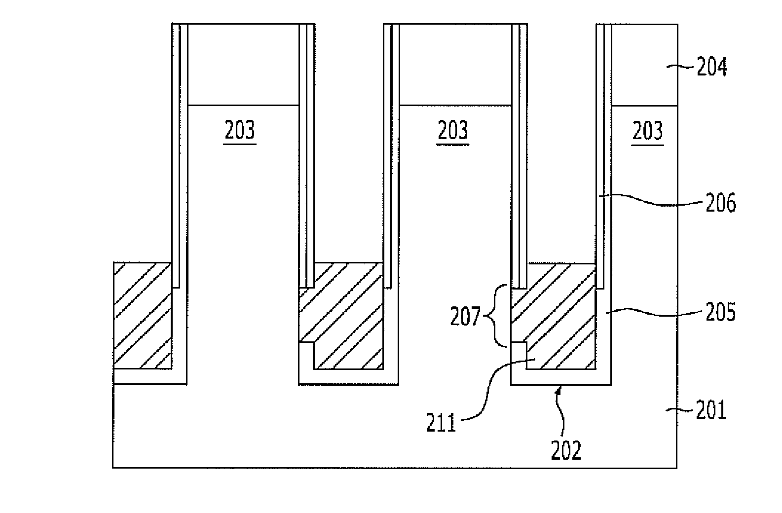
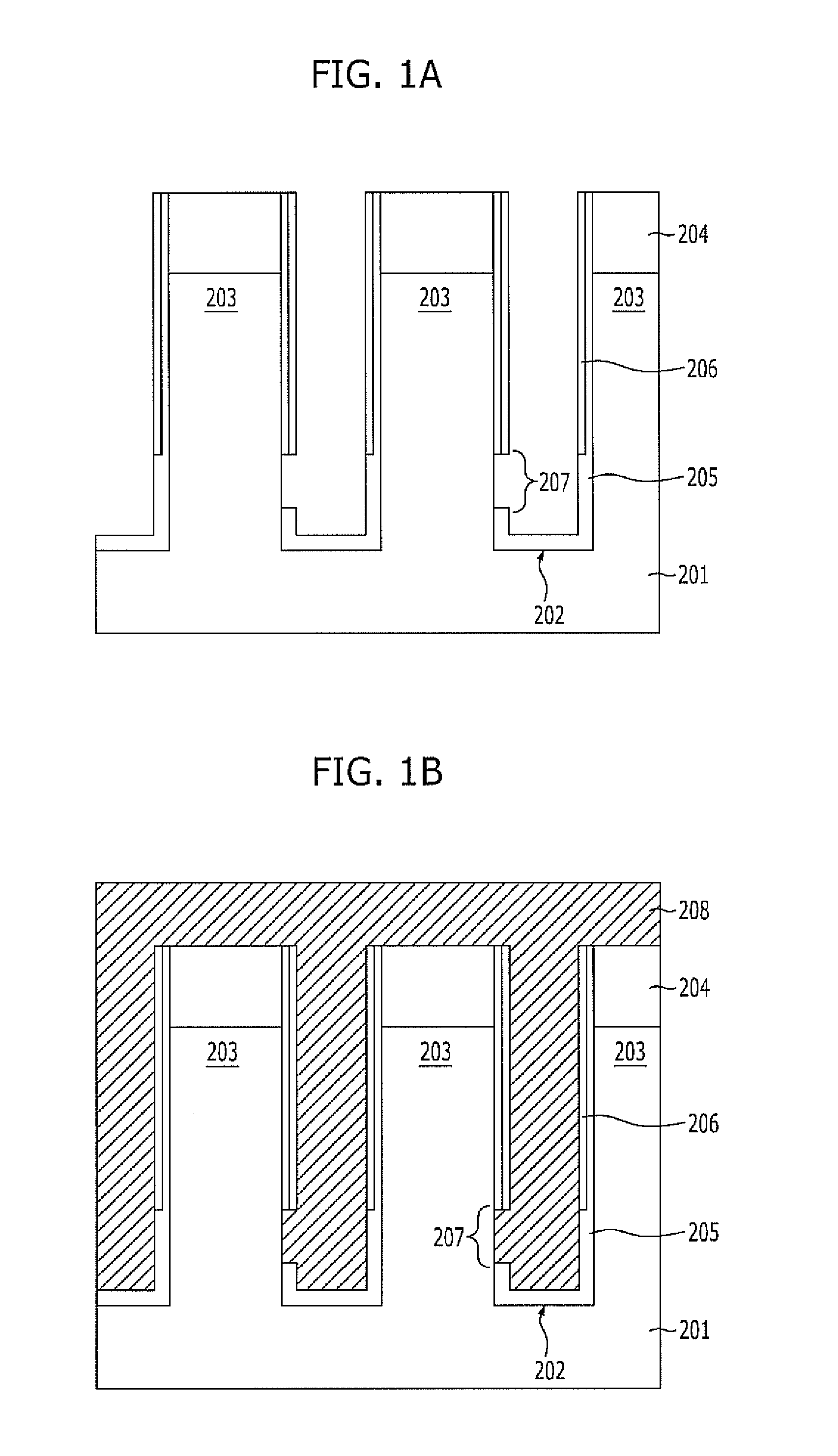
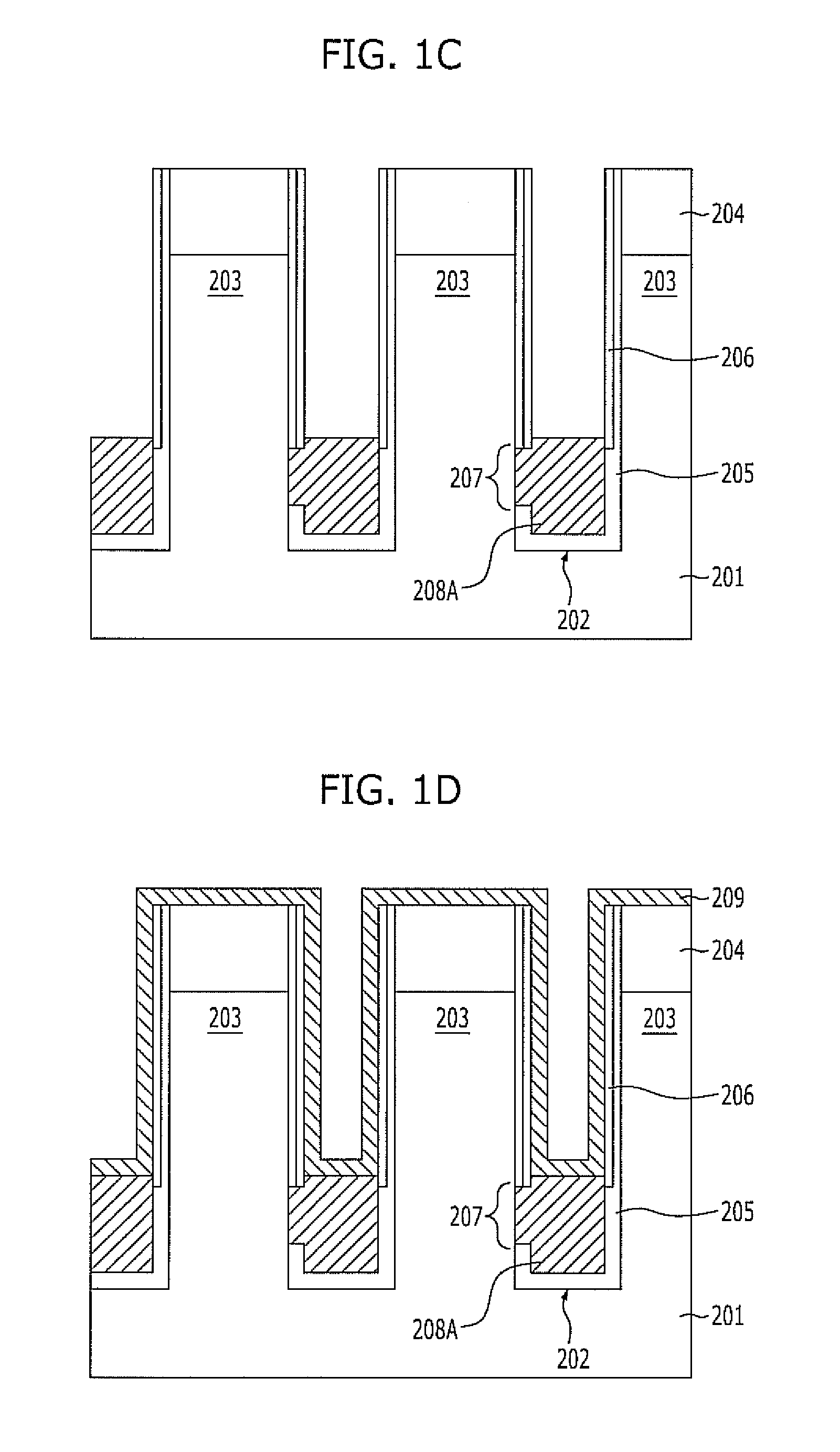
[0019]Exemplary embodiments of the present invention will be described below in more detail with reference to the accompanying drawings. The present invention may, however, be embodied in different forms and should not be construed as limited to the embodiments set forth herein.

[0020]Rather, these embodiments are provided so that this disclosure will be thorough and complete, and will fully convey the scope of the present invention to those skilled in the art. Throughout the disclosure, like reference numerals refer to like parts throughout the various figures and embodiments of the present invention.

[0021]The drawings are not necessarily to scale and in some instances, proportions may have been exaggerated in order to clearly illustrate features of the embodiments. When a first layer is referred to as being “on” a second layer or “on” a substrate, it not only refers to a case where the first layer is formed directly on the second layer or the substrate but also a case where a third...


PUM


Abstract

A method for fabricating a semiconductor device includes etching a substrate to form trenches that separate active regions, forming an insulation layer having an opening to open a portion of a sidewall of each active region, forming a silicon layer pattern to gap-fill a portion of each trench and cover the opening in the insulation layer, forming a metal layer over the silicon layer pattern, and forming a metal silicide layer as buried bit lines, where the metal silicide layer is formed when the metal layer reacts with the silicon layer pattern.

Description

CROSS-REFERENCE TO RELATED APPLICATIONS[0001]The present application claims priority of Korean Patent Application No. 10-2010-0139486, filed on Dec. 30, 2010, which is incorporated herein by reference in its entirety.BACKGROUND OF THE INVENTION[0002]Exemplary embodiments of the present invention relate to a method for fabricating a semiconductor device, and more particularly, to a method for fabricating a semiconductor device with buried bit lines.[0003]As the degree of integration for Dynamic Random Access Memory (DRAM) devices increases, two-dimensional (2D) structures are reaching limits. Thus, three-dimensional (3D) DRAMs with vertical gates (VG), which are referred to hereinafter as VG DRAM, are being developed.[0004]A 3D DRAM having a vertical gate structure may include active regions, each of which is formed of a body and a pillar formed over the body, buried bit lines BBL, and vertical gates VG. The bodies of adjacent active regions are separated from each other by a trench ...

Claims


Application Information

Patent Timeline
IPC IPC(8): H01L21/20
CPCH01L27/10885H01L21/743H10B12/482
Inventor HWANG, EUI-SEONG
Owner SK HYNIX INC
Why Eureka
Try Eureka