
Memory system and method of operating the same

a memory system and memory technology, applied in the field of memory systems, can solve the problem that the error correction operation cannot be applied to a memory cell block having a large number of error bits

Inactive Publication Date: 2012-07-05
SK HYNIX INC
View PDF10 Cites 37 Cited by
  • Summary
  • Abstract
  • Description
  • Claims
  • Application Information

AI Technical Summary

Problems solved by technology

The error correction operation cannot be applied to a memory cell block having a large number of error bits.

Method used


Image

  • Memory system and method of operating the same
  • Memory system and method of operating the same
  • Memory system and method of operating the same

Examples


Embodiment Construction

[0020]Hereinafter, some exemplary embodiments of the present disclosure will be described in detail with reference to the accompanying drawings. The figures are provided to allow those having ordinary skill in the art to understand the scope of the embodiments of the disclosure.

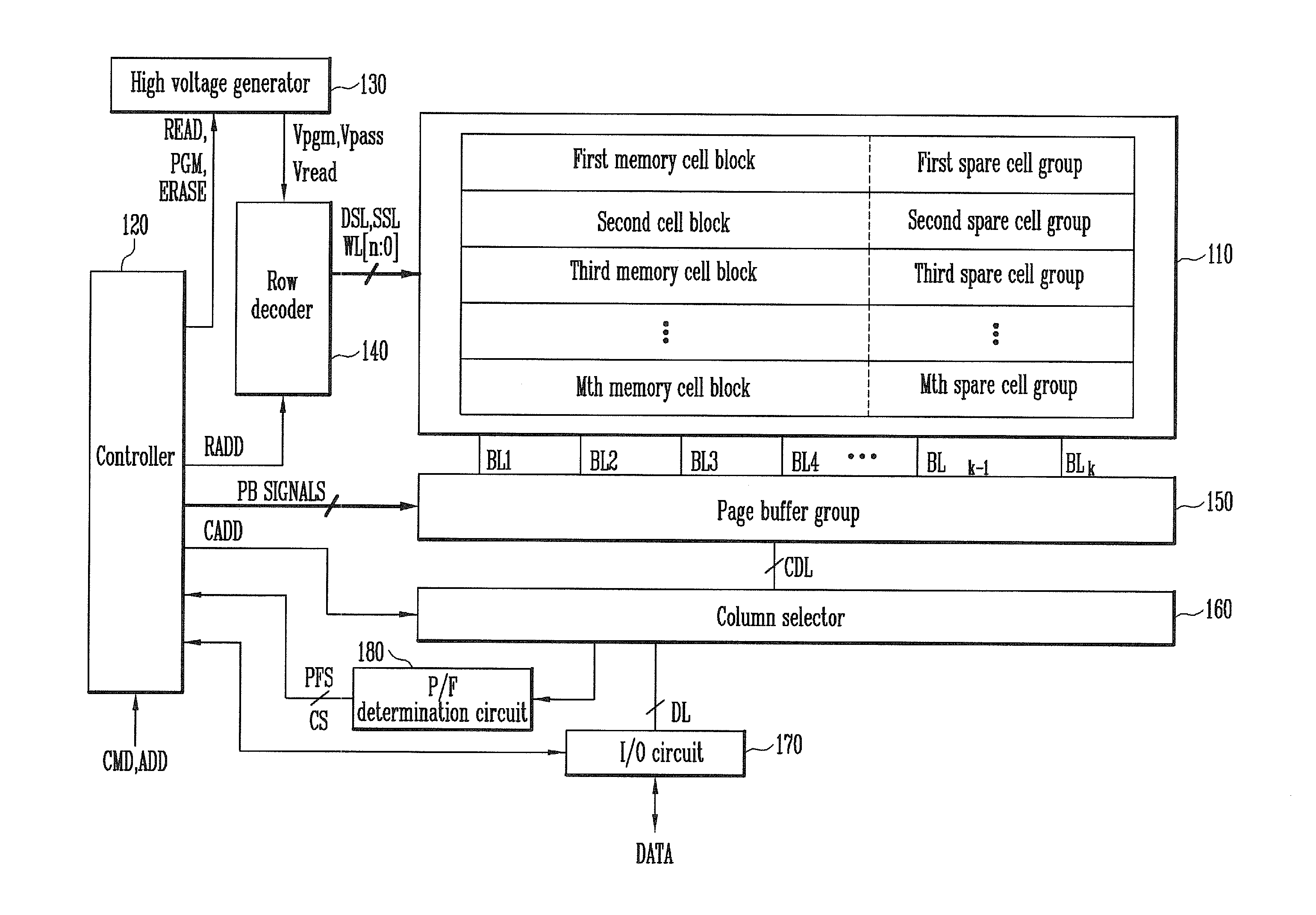
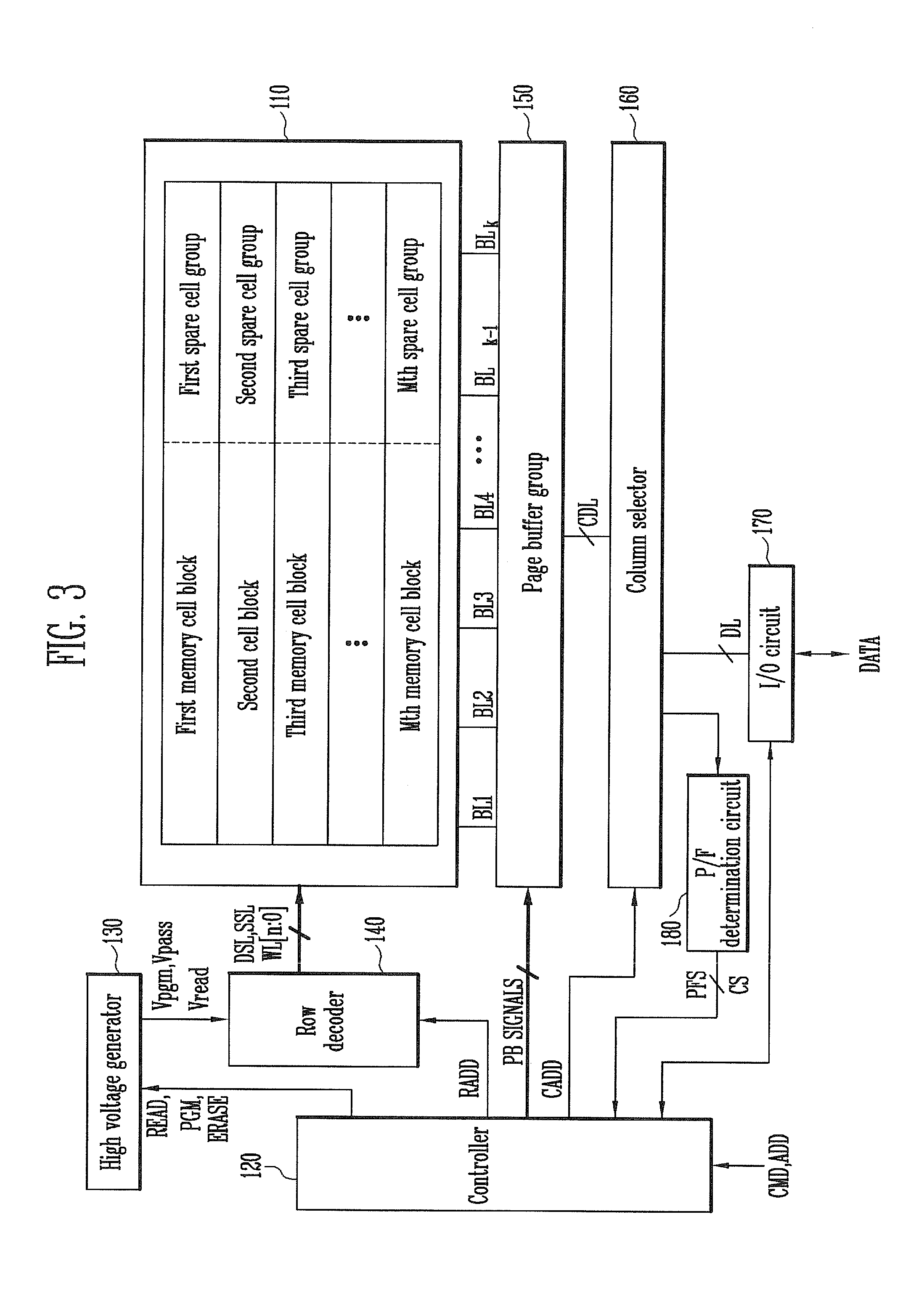
[0021]FIG. 3 is a diagram illustrating a memory system according to this disclosure.

[0022]Referring to FIG. 3, the memory system includes a memory cell array 110, an operation circuit group (130, 140, 150, 160, 170, and 180) for performing a program operation or a read operation for the memory cells of the memory cell array 110, and a controller 120 for controlling the operation circuit group (130, 140, 150, 160, 170, and 180) so that a program verification operation is performed in order so that memory cells programmed with a higher level are verified later.

[0023]In the case of a NAND flash memory device, the operation circuit group includes a high voltage generator 130, a row decoder 140, a page buffer grou...


PUM


Abstract

A method of operating a memory system includes classifying numbers of total error bits into a plurality of ranges, assigning a plurality of data to the plurality of ranges, respectively, counting a number of detected error bits for a memory cell block, and storing a selected one of the plurality of data in at least one spare cell when the number of the detected error bits is within one of the ranges that corresponds to the selected data.

Description

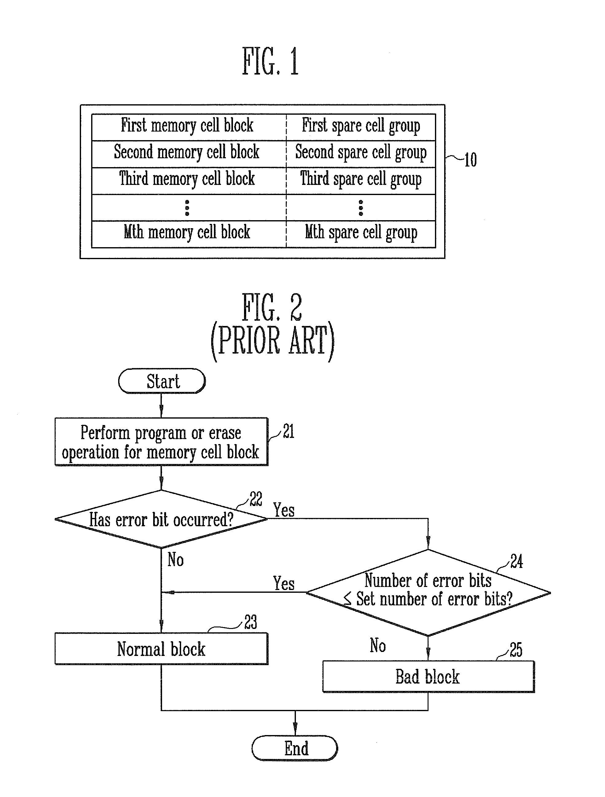
CROSS-REFERENCE TO RELATED APPLICATION[0001]Priority to Korean patent application number 10-2010-0139185 filed on Dec. 30, 2010, the entire disclosure of which is incorporated by reference herein, is claimed.BACKGROUND[0002]Exemplary embodiments relate to a memory system and a method of operating the same and, more particularly, to a memory system for classifying memory cell blocks according to the number of error bits and a method of operating the same.[0003]After a semiconductor memory device is fabricated, a test operation for determining whether the memory cell blocks of the semiconductor memory device belong to a normal block and an unusable bad block is performed. The test operation may be performed in various ways. One of the methods is to perform a test program operation or a test erase operation using test data. This method is described below.[0004]FIG. 1 is a diagram illustrating a memory cell array.[0005]Referring to FIG. 1, a semiconductor memory device includes a memory...

Claims


Application Information

Patent Timeline
Patent Type & Authority Applications(United States)
IPC IPC(8): G06F11/07G06F11/20
CPCG11C16/349G11C16/3495G11C29/42G11C2029/0411G11C29/82G11C2029/0409G11C29/4401
Inventor PARK, SEONG HUN
Owner SK HYNIX INC
Learn More