Guidance control for spinning or rolling vehicle

a technology of steering control and spinning wheels, applied in the direction of ammunition fuzes, instruments, transportation and packaging, etc., can solve the problems of heat dissipation problems, insufficient braking force, and inability to accurately correct course corrections

Active Publication Date: 2012-07-12
RAYTHEON CO
View PDF5 Cites 21 Cited by
  • Summary
  • Abstract
  • Description
  • Claims
  • Application Information

AI Technical Summary

Problems solved by technology

However, these devices suffer from significant disadvantages, such as the danger of premature explosion, and the shock caused by these devices often leads to imprecise course corrections.
However this requires sufficient braking force to restrain a section substantially stationary relative to a spinning or rolling fuselage or body.
This can result in a heat dissipation problem, among other issues.

Method used


Image

  • Guidance control for spinning or rolling vehicle
  • Guidance control for spinning or rolling vehicle
  • Guidance control for spinning or rolling vehicle

Examples


Embodiment Construction

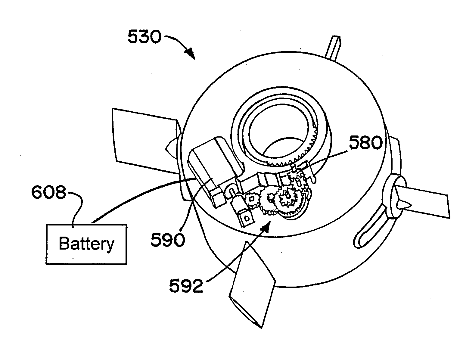
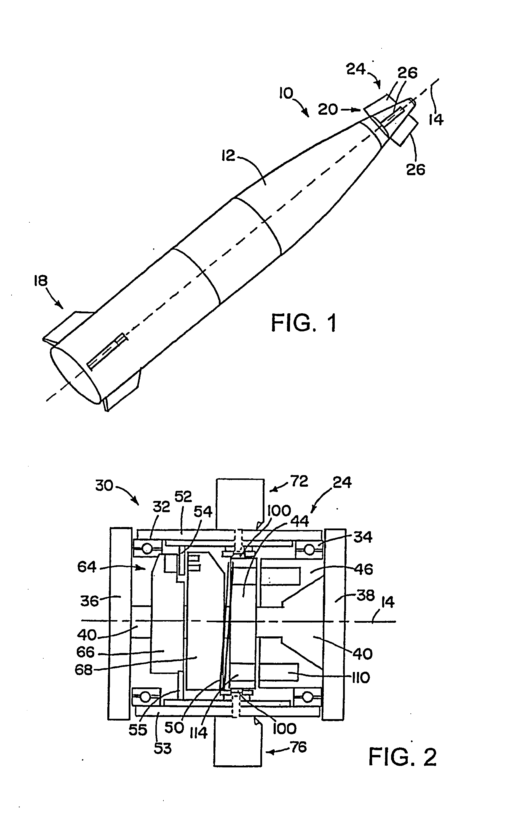
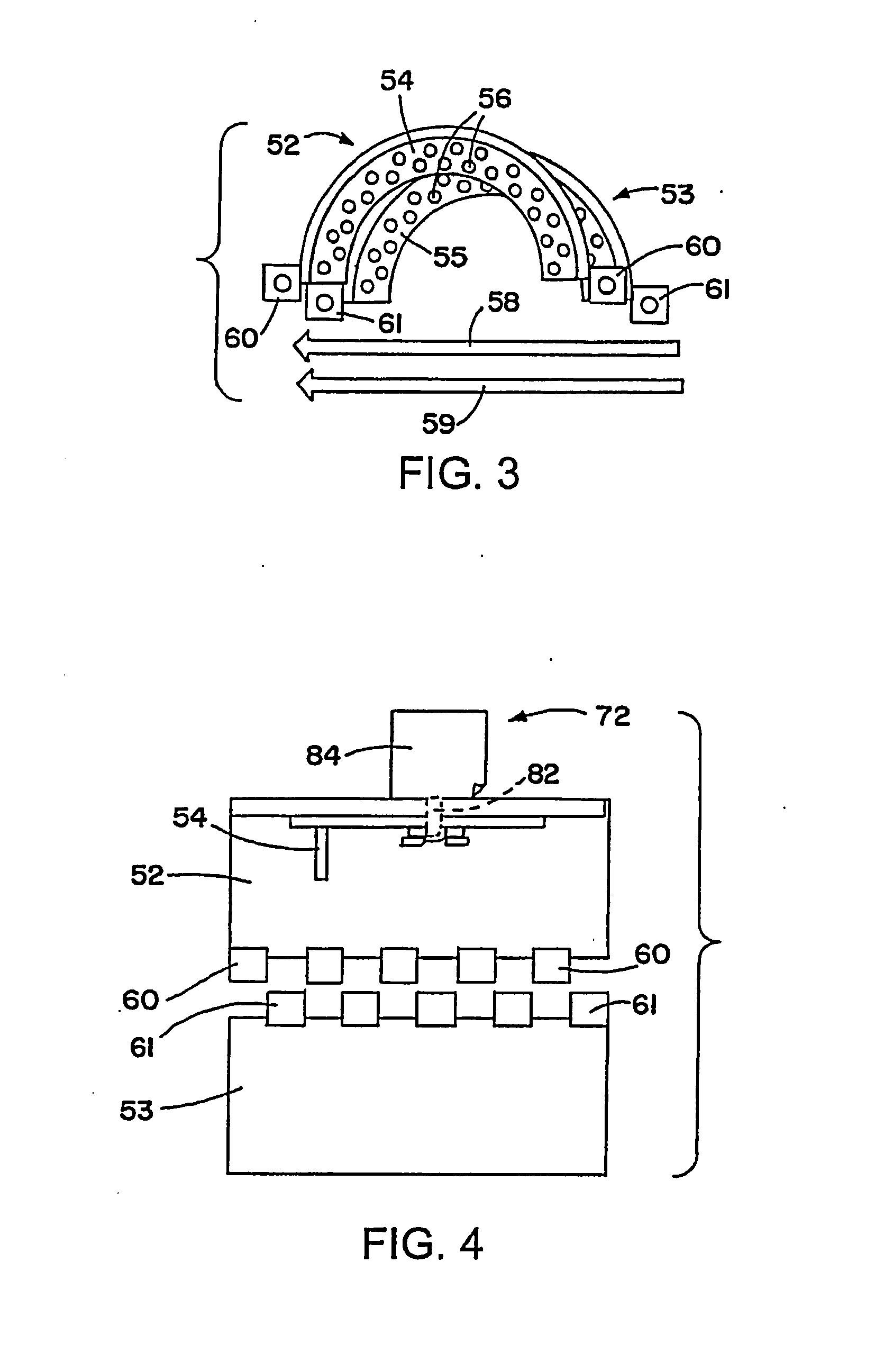
[0042]A projectile, air vehicle or submersible craft with a spinning or rolling fuselage, rotating on its axis, has a collar which can be positioned relative to a longitudinal axis of the projectile using aerodynamic forces. Aerodynamic surfaces, such as lift-producing surfaces, for example tails or canards, are coupled to the collar, and rotate with the collar. An actuator system or mechanism controls orienting of the lift-producing surfaces, such as tilting of the lift producing surfaces, to direct the collar into a desired position relative to a longitudinal axis of the projectile, and to maintain the collar in that position. With such a control the projectile is able to be steered using bank-to-turn maneuvering. The actuator system may use any of a variety of mechanisms to move the lift-producing surfaces, thereby positioning the collar.

[0043]FIG. 1 shows a spin-stabilized projectile 10 that has a fuselage 12 that spins during flight, rotating about a longitudinal axis 14 of the...


PUM


Abstract

A projectile, air vehicle or submersible craft with a spinning or rolling fuselage, rotating on its axis, has a collar which can be positioned relative to a longitudinal axis of the projectile using aerodynamic forces. Aerodynamic surfaces, such as lift-producing surfaces, for example tails or canards, are coupled to the collar, and rotate with the collar. An actuator system or mechanism controls orienting of the lift-producing surfaces, such as tilting of the lift producing surfaces, to direct the collar into a desired position relative to a longitudinal axis of the projectile, and to maintain the collar in that position. With such a control the projectile is able to be steered using bank-to-turn maneuvering. The actuator system may use any of a variety of mechanisms to move the lift-producing surfaces, thereby positioning the collar.

Description

[0001]This application is a continuation-in-part of U.S. application Ser. No. 13 / 005,175, filed Jan. 12, 2011, which is incorporated herein by reference in its entirety.BACKGROUND OF THE INVENTION[0002]1. Field of the Invention[0003]The invention is in the field of control systems for spinning, rolling, or roll stabilized vehicles, either airborne or submersible, such as spinning projectiles / missiles.[0004]2. Description of the Related Art[0005]In certain military applications, there is a significant need for “smart” projectiles wherein the operator can effectively control the course the projectile takes and the target location that is impacted. Such navigational control requires the ability to impart precise forces to a rapidly spinning projectile with respect to the Earth inertial frame to achieve a desired directional course. Some past devices have used arrays of propulsive outlets, fuels and pyrotechnics to produce the necessary forces for the desired two-dimensional course corr...

Claims


Application Information

Patent Timeline
Patent Type & Authority Applications(United States)
IPC IPC(8): F42B15/01G02B7/04F42B10/00F42C14/00B64C13/00
CPCF42B10/26G02B23/16G02B7/022F42B10/62
Inventor GESWENDER, CHRIS E.ALEJANDRO, STEVIEVESTY, PAUL
Owner RAYTHEON CO
Why Eureka
Try Eureka