Lamp unit

a technology of lamp units and lamps, which is applied in the direction of point-like light sources, transportation and packaging, light and heating equipment, etc., can solve the problems of increasing assembly overhead and relatively complex structure of lamp units of this type, and achieves the effect of simple structure and less assembly effor

Inactive Publication Date: 2012-07-12
OSRAM GMBH
View PDF8 Cites 1 Cited by
  • Summary
  • Abstract
  • Description
  • Claims
  • Application Information

AI Technical Summary

Benefits of technology

[0006]Accordingly, the object of the invention is to create a lamp unit which has a simple structure and can be assembled with little effort.

Problems solved by technology

A disadvantage with said solutions is that firstly lamp units of this type are relatively complex in terms of their structure, since the additional components must be provided for ensuring correct positional fixing.
Secondly, the assembly overhead is increased due to the attachment of the additional components.

Method used


Image

  • Lamp unit
  • Lamp unit
  • Lamp unit

Examples


Embodiment Construction

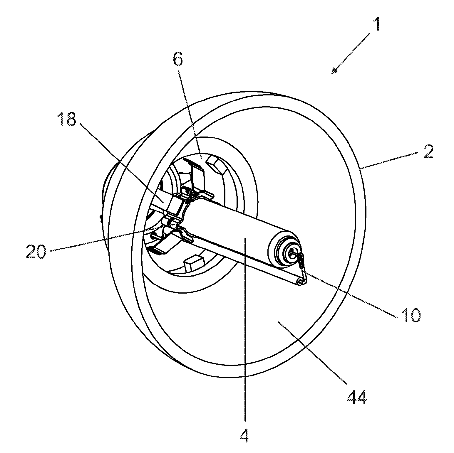
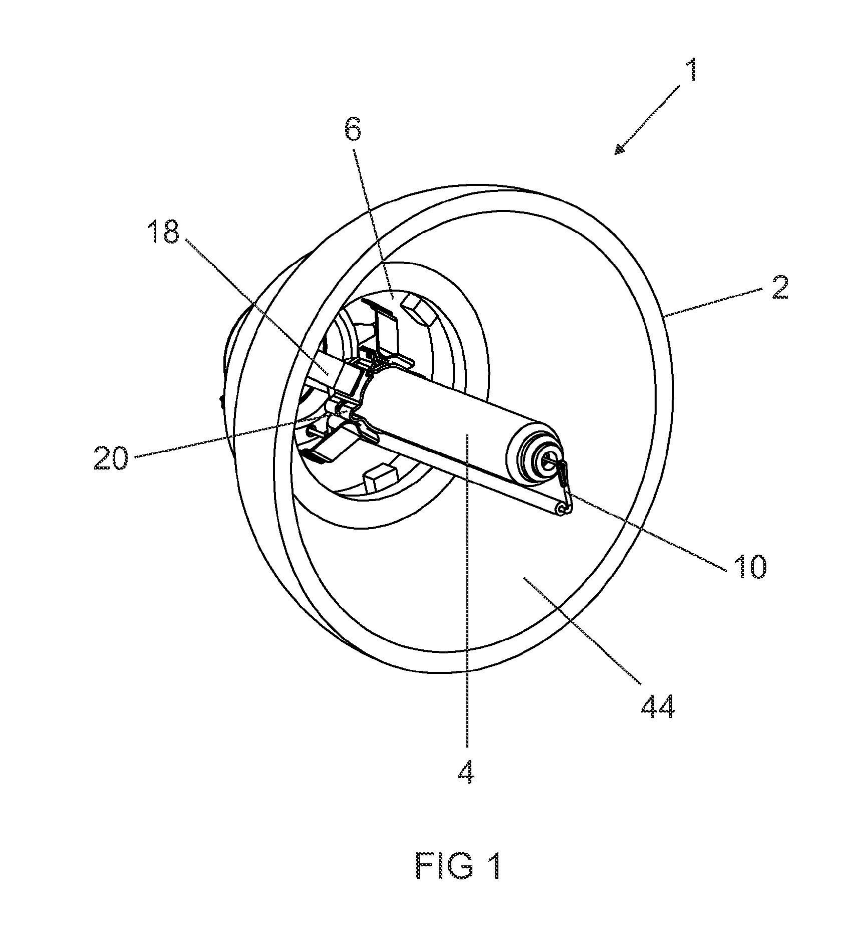
[0042]FIG. 1 shows a three-dimensional view of a lamp unit 1 according to the invention, including a high-pressure discharge lamp 4 inserted into a reflector 2 of a motor vehicle headlight. Said lamp can be for example a metal halide high-pressure discharge lamp having an electrical power draw of approx. 25 W or a D1 to D4 lamp. High-pressure discharge lamps of this type are sufficiently well-known from the prior art, for example from EP 1 605 490 A2 or EP 0 786 791 B1, so only the components essential to an understanding of the invention will be explained here and otherwise reference will be made to the cited prior art.

[0043]The special feature of the lamp unit 1 shown in FIG. 1 consists in the fact that the reflector 2 and the high-pressure discharge lamp 4 are connected to each other by means of a bayonet coupling 6, the difference compared to conventional solutions being that additional components such as clips, brackets or coupling cages are dispensed with.

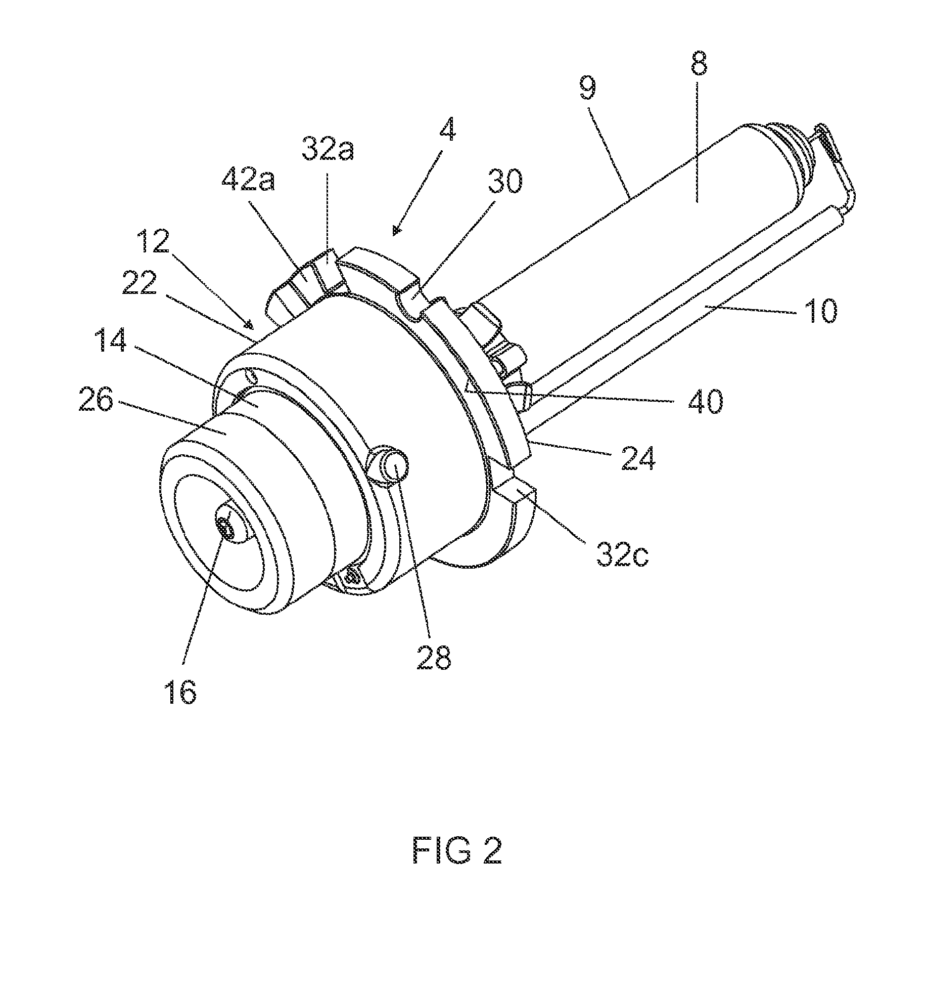
[0044]FIG. 2 shows an...


PUM


Abstract

In various embodiments, a lamp unit including a lamp which is inserted into a reflector and which has a base with a reference ring including at least one referencing surface which cooperatively interacts with a corresponding referencing element of a holder of the reflector, configured such that the lamp is separably connected to the holder through a bayonet coupling.

Description

TECHNICAL FIELD[0001]The invention relates to a lamp unit according to the preamble of claim 1.BACKGROUND ART[0002]A lamp unit of said type can in principle be used in a multiplicity of single-ended lamps. However, the main field of application is most likely to be in lamp units for vehicle headlights. A lamp unit for such motor vehicle headlights is described for example in EP 1 605 490 A2 and DE 10 2005 009 902 A1.[0003]In these known solutions the lamp unit has a discharge lamp, such as is marketed for example under the product name “Xenarc™”. Said high-pressure discharge lamp has a single-part or multipart lamp base by way of which it can be inserted into a holder of a reflector of a motor vehicle headlight. In order to align the lamp in the reflector and prevent incorrect installation of different lamp types, one or more referencing and coding recesses are embodied on a referencing ring of the base, which recesses cooperatively interact with corresponding projections on the hol...

Claims


Application Information

Patent Timeline
Patent Type & Authority Applications(United States)
IPC IPC(8): F21V7/00F21Y101/00
CPCF21S48/1145F21S48/1109F21S41/14F21S41/192
Inventor BECKER, JUERGENKLAGES, KILIANPIETSCH, KARSTENPROTSCH, MATTHIAS
Owner OSRAM GMBH
Why Eureka
Try Eureka