Variable carbonation using in-line carbonator

a carbonator and variable technology, applied in the direction of liquid transfer devices, combustible gas purification/modification, separation processes, etc., can solve the problems of large carbonation tanks, increased manufacturing costs of beverage dispensers, and failure modes of carbonated beverage systems that require an expensive replacement of components

Inactive Publication Date: 2012-07-12
MARMON FOODSERVICE TECH INC
View PDF2 Cites 20 Cited by
  • Summary
  • Abstract
  • Description
  • Claims
  • Application Information

AI Technical Summary

Problems solved by technology

Typically such carbonator tanks are bulky and large and increase the manufacturing cost of a beverage dispensing system.
Additionally, a large carbonation tank significantly increases the footprint or size of a drink dispenser.
Further, large carbonation tanks may provide a failure mode for a carbonated beverage system requiring an expensive replacement of the component.

Method used


Image

  • Variable carbonation using in-line carbonator
  • Variable carbonation using in-line carbonator
  • Variable carbonation using in-line carbonator

Examples


Embodiment Construction

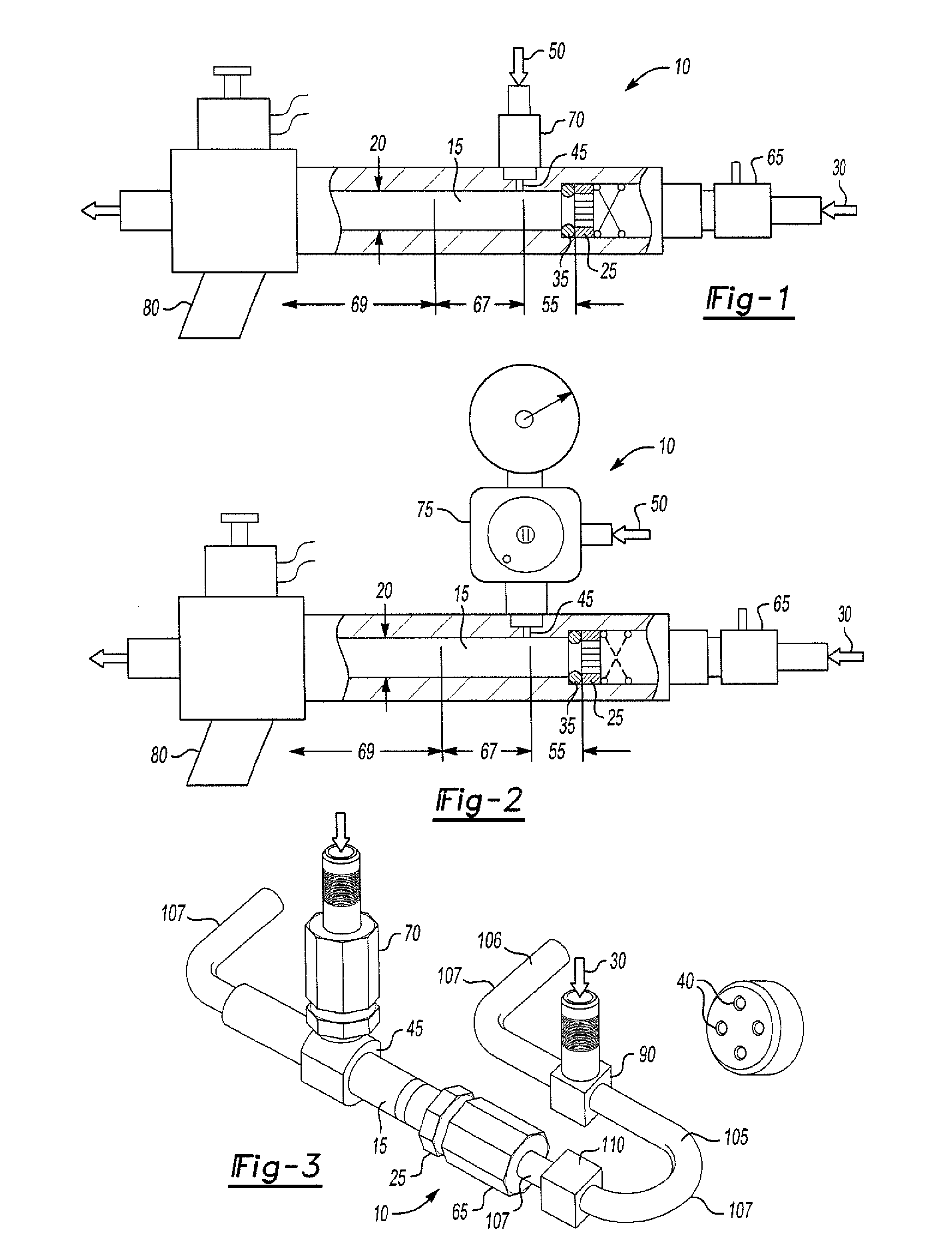
[0023]Referring to FIG. 1, there is shown an inline carbonation apparatus 10 that includes a fluid tube 15 having an inner diameter 20. At least one water orifice 25 is linked to a water source 30 and is attached at one end 35 of the fluid tube 15. The water orifice 25 may have a plurality of holes 40 that atomize water passing therethrough. A carbon dioxide orifice 45 is linked to a carbon dioxide source 50 and is attached to the fluid tube 15 in a spaced relationship from the water orifice 25. The atomized water exiting the water orifice 25 has a pressure that is less than the carbon dioxide such that carbon dioxide is absorbed into the water forming carbonated water having a specified volume of carbonation.

[0024]In one aspect, the carbon dioxide orifice 45 is spaced from the water orifice 25 a distance of from one quarter to three quarters of the diameter 20 of the fluid tube 15. This spacing defines a first free jet zone 55 within the inline carbonation apparatus 10. In one aspe...


PUM

PropertyMeasurementUnit
sizeaaaaaaaaaa
sizeaaaaaaaaaa
pressureaaaaaaaaaa

Abstract

An inline carbonation apparatus includes a fluid tube having an inner diameter. At least one water orifice is linked to a water source and is attached at one end of the fluid tube. The water orifice atomizes water passing therethrough. A carbon dioxide source is connected to a carbon dioxide solenoid valve. The carbon dioxide solenoid valve is connected to a carbon dioxide regulator that is coupled to a carbon dioxide orifice and attached to the fluid tube in a spaced relationship from the water orifice. The atomized water has a pressure less than the carbon dioxide such that carbon dioxide is absorbed into the water forming carbonated water having a specified volume of carbonation. The carbon dioxide solenoid valve is opened and closed for a predetermined portion of a drink dispense time providing a volume of carbonated and non-carbonated fluid which upon mixing achieves a desired carbonation level.

Description

CROSS-REFERENCE TO RELATED APPLICATIONS[0001]This application claims priority of U.S. Provisional Application No. 61 / 398,631 filed Jun. 29, 2010 and U.S. Utility application Ser. No. 13 / 171,957 filed Jun. 29, 2011, which are incorporated herein by reference.FIELD OF THE INVENTION[0002]The invention relates to carbonation apparatus and a method for forming a carbonated beverage.BACKGROUND OF THE INVENTION[0003]Generally it is known to provide carbonated beverages that utilize carbonated water. The carbonated water is generally formed using a carbonator tank into which water under pressure is introduced into the tank with carbon dioxide also under pressure. The pressure of the contents of the vessel forces the carbon dioxide into the water forming a carbonated water. Typically such carbonator tanks are bulky and large and increase the manufacturing cost of a beverage dispensing system. Additionally, a large carbonation tank significantly increases the footprint or size of a drink disp...

Claims


Application Information

Patent Timeline
Patent Type & Authority Applications(United States)
IPC IPC(8): A23L2/54B67D7/08B01F3/04B67D7/74
CPCA23L2/54B01F3/04758B01F2215/0468B01F3/04815B01F2215/0431B01F3/04808B01F23/23413B01F23/2363B01F23/2362
Inventor MALAGI, JAYATEERTHASERVESH, A.R.
Owner MARMON FOODSERVICE TECH INC
Why Eureka
Try Eureka