Anchor bracket and method of mounting anchor bracket

Active Publication Date: 2012-07-19
BUTTNER RONALD +1
View PDF20 Cites 1 Cited by
  • Summary
  • Abstract
  • Description
  • Claims
  • Application Information

AI Technical Summary

Benefits of technology

[0008]It is a further object to provide an anchor bracket which can be easily mounted between a pair of spaced-apart boards, namely of a deck, for the releasable anchoring of an object thereto.
[0010]It is another object of the invention to provide a one-piece anchor bracket which is easy to manufacture.
[0011]It is still another object to provide an anchor bracket which can be mounted between spaced-apart boards without leaving any holes or damaging marks on the surface of the boards.
[0012]It is yet another object of the invention to provide an easy and facile method of mounting the anchor bracket between spaced-apart boards.

Problems solved by technology

However, conventional fastening or anchoring means often result in damage to the deck or fence via. e.g., nicking, scratching, and in many cases require nailing or the formation of holes in the deck or fence to mount the fastener.
Normally, to anchor a tarp to the pool deck requires the fastener to be mounted via a bore or hole in the surface of the deck, which obviously damages the deck, or they otherwise leave behind other damaging marks on the surface of the deck when being mounted or in operation.

Method used


Image

  • Anchor bracket and method of mounting anchor bracket
  • Anchor bracket and method of mounting anchor bracket
  • Anchor bracket and method of mounting anchor bracket

Examples


Embodiment Construction

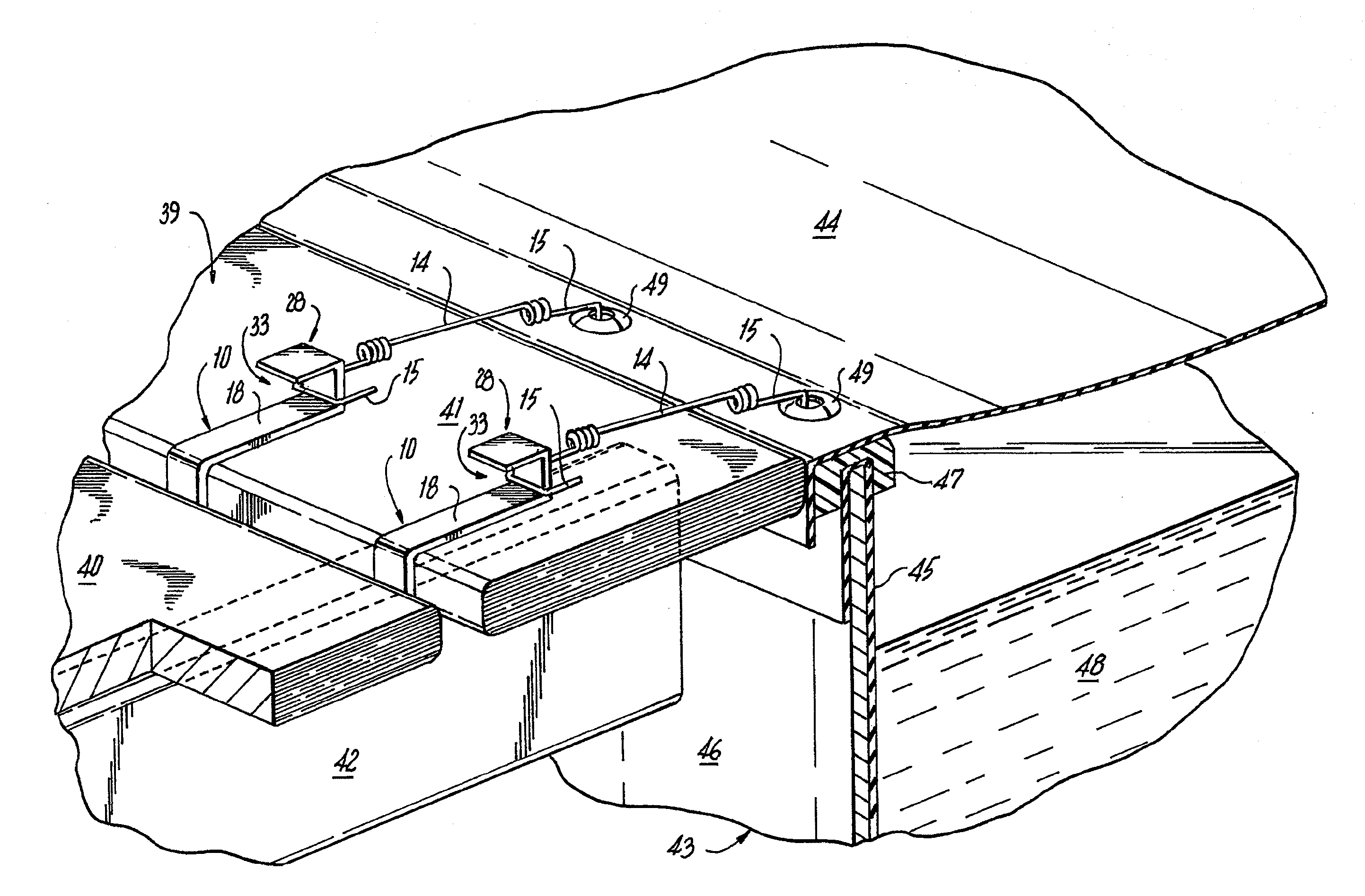
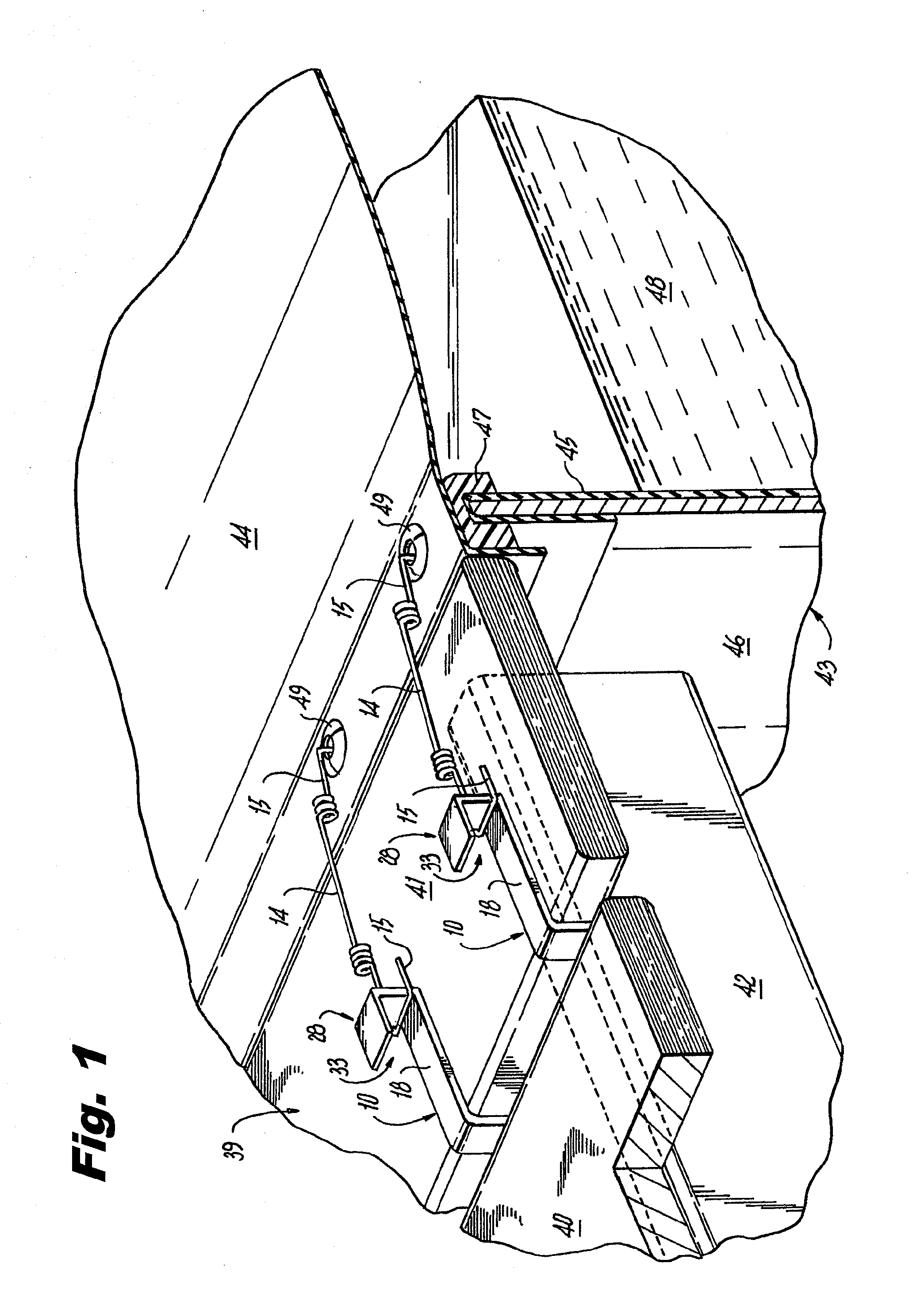
[0033]Referring to FIGS. 1-5, therein illustrated is a first embodiment of the anchor bracket of the present invention, generally designated by reference numeral 10, which is removably securable between two adjacent, spaced apart boards 40, 41 of a deck for releasable attachment to a tarp or pool cover 44 of a pool 43 having a sidewall 46 over the upper rim of which is draped the periphery of plastic pool liner 45, which is held in place via a U-shaped pool edge cap 47. As is typical in most cases, even in the off season, the pool 43 remains filled with water 48. The periphery of the pool cover 44 is provided with multiple spaced-apart grommets 49 by which the pool cover 44 can be fastened to the surrounding pool deck 39.

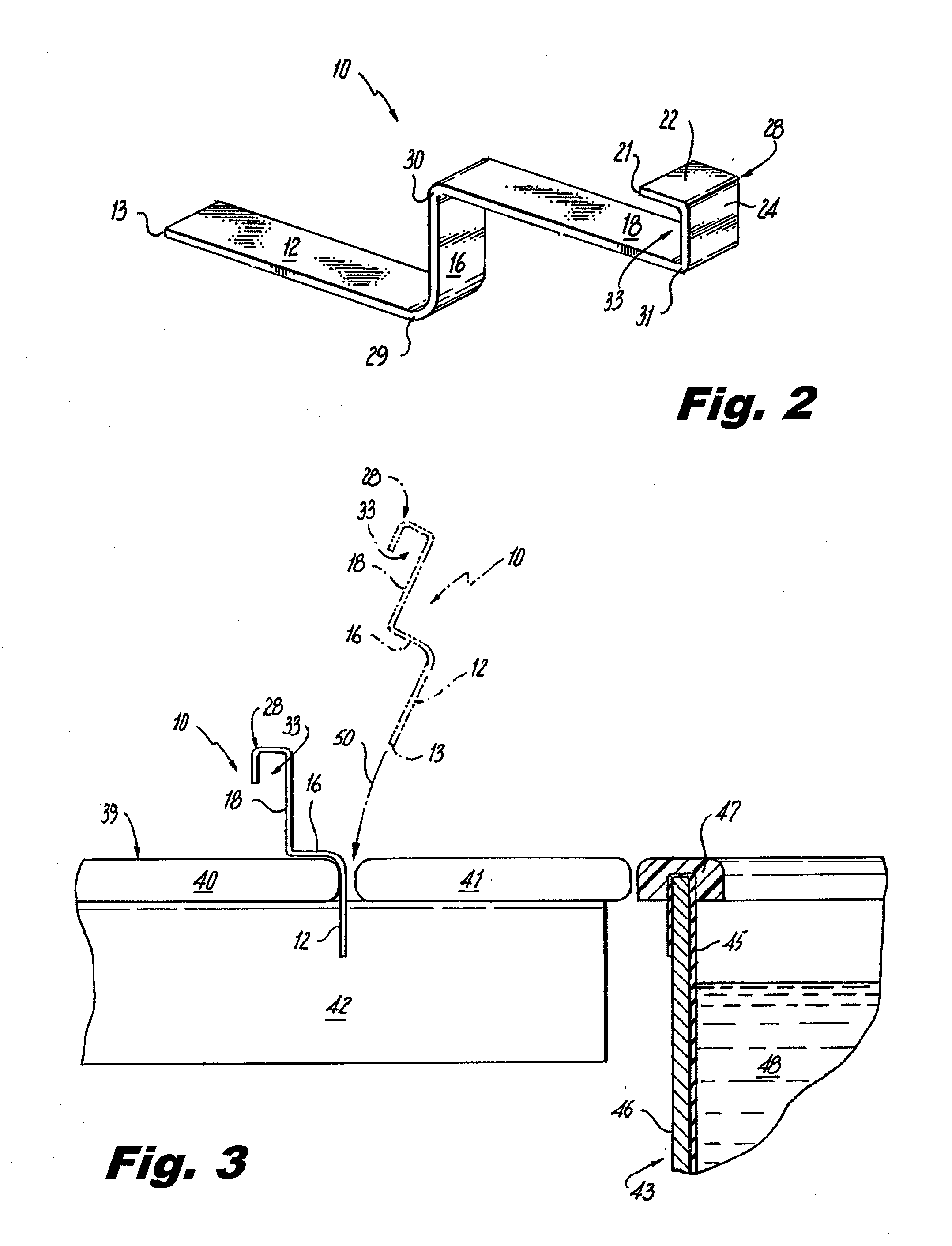
[0034]As seen best in FIG. 2, a preferably one-piece anchor bracket 10 comprises a planar lower leg 12, a planar upper leg 18, a medial shank 16, and a L-shaped hooked end 28. Anchor bracket 10 has a generally reverse Z-shaped profile, with upper leg 18 and lower le...


PUM

PropertyMeasurementUnit
Angleaaaaaaaaaa
Radiusaaaaaaaaaa
Elasticityaaaaaaaaaa

Abstract

An anchor bracket releasably securable between two spaced-apart, generally planar boards, having a pair of first and second legs disposed parallel and offset relative to one another, a medial shank disposed between and generally perpendicular to and joining the pair of legs and means for releasably anchoring an object attached to the second leg. A method of mounting the anchor bracket includes the steps of moving the anchor bracket between an insertion / withdrawal position and a mounted anchoring position between a pair of spaced-apart boards.

Description

CROSS-REFERENCE TO RELATED APPLICATION[0001]This application claims benefit from U.S. Provisional Patent Application No. 61 / 461,156, filed Jan. 14, 2011 the contents of which are hereby incorporated by reference.BACKGROUND OF THE INVENTION[0002]1. Field of the Invention[0003]The invention relates generally to removable fastening devices. More particularly, the invention relates to an anchor bracket removably securable between at least two spaced-apart boards for the releasable anchoring of an object to the anchor bracket. In addition, the invention relates to a method of mounting the anchor bracket between spaced-apart boards, and thereafter releasably anchoring an object to the anchor bracket.[0004]2. Brief Description of the Prior Art[0005]For homeowners, or other individuals, where two or more spaced-apart boards are provided as a supportive or anchoring surface, e.g. a deck or fence, the need to anchor certain items which are placed either thereon or nearby frequently arises. Ho...

Claims


Application Information

Patent Timeline
IPC IPC(8): F16B1/00F16B45/00B23P11/00F16B17/00
CPCE04H4/06E04H4/10E04H17/14F16B5/0635Y10T403/57Y10T29/49948Y10T29/49947Y10T403/70Y10T29/49826F16B5/0692
Inventor BUTTNER, RONALDBUTTNER, RANDALL
Owner BUTTNER RONALD
Why Eureka
Try Eureka