Floor Panel and Floor Covering Consisting of a Plurality of Such Floor Panels

a technology of floor panels and floor coverings, applied in the field of floor panels, to achieve the effect of facilitating the coupling of floor panels, preventing the scraping of (the upper surface of) the floor panels against each other, and enhancing the durability of the coupling parts

Active Publication Date: 2012-07-19
I4F LICENSING NV
View PDF3 Cites 100 Cited by
  • Summary
  • Abstract
  • Description
  • Claims
  • Application Information

AI Technical Summary

Benefits of technology

[0028]The invention further relates to a method for mutually connecting two floor panels according to the invention, comprising the steps of: A) having a second coupling part of a first floor panel engage on a first coupling part of a second floor panel, B) exerting a force on the second coupling part of the first floor panel in the direction of the first coupling part of the second floor panel, such that an end part of the second coupling part of the first floor panel will pivot in upward direction and/or an end part of the first coupling part of the second floor panel will pivot in a downward direction, whereby a downward tongue of the second coupling part of the first floor panel is arranged at least partially, in particular substantially, in an upward groove of the first coupling part of the second floor panel, and C) releasing the force exerted during step B), whereby the at least one deformed coupling part will pivot back to an initial position and the downward tongue of the second coupling part of the first floor panel will be locked in the upward groove of the first coupling part of the second floor panel. During step A) an intermediate state is realized wherein the floor panels are pre-aligned with respect to each other. During step B) a substantially linear displacement of the floor panels relative to each other will generall

Problems solved by technology

This is because, owing to the characteristic inclining orientation of the tongue walls facing toward the respective flanks, the exerting of (for instance) a vertical force on the coupling is not likely to result in an uncoupli

Method used


Image

  • Floor Panel and Floor Covering Consisting of a Plurality of Such Floor Panels
  • Floor Panel and Floor Covering Consisting of a Plurality of Such Floor Panels
  • Floor Panel and Floor Covering Consisting of a Plurality of Such Floor Panels

Examples


Embodiment Construction

)

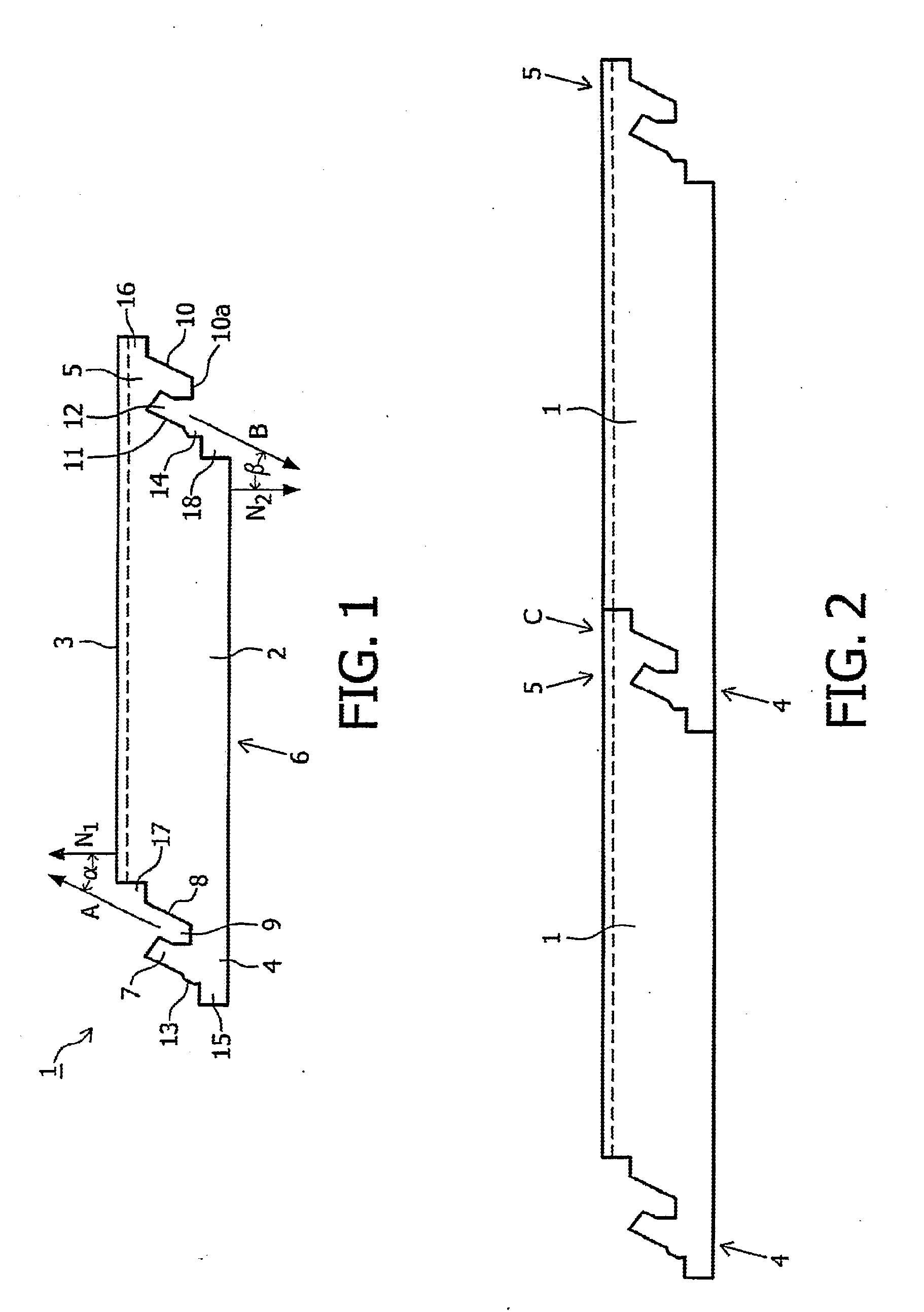
[0050]FIG. 1 shows a side view of a floor panel 1 according to the invention. Floor panel 1 comprises a plate-like core 2 which is manufactured from fiberboard, in particular MDF (Medium Density Fiberboard) or HDF (High Density Fiberboard) or chipboard and on which a top layer 3 is arranged. The opposite longitudinal sides of core 2 are provided with a first coupling part 4 and a second coupling part 5. The part of floor panel 1 lying between first coupling part 4 and second coupling part 5, as indicated by means of the broken lines, forms the central part 6 of floor panel 1. First coupling part 4 comprises an upward tongue 7, an upward flank 8 and an upward groove 9 formed between upward tongue 7 and upward flank 8. Second coupling part 5 comprises a downward tongue 10, a downward flank 11 and a downward groove 12 formed between downward tongue 10 and downward flank 11. As shown, upward tongue 7, upward flank 8 and upward groove 9 extend in the direction (indicated by means of arr...


PUM

PropertyMeasurementUnit
Angleaaaaaaaaaa
Angleaaaaaaaaaa
Angleaaaaaaaaaa

Abstract

The invention relates to a floor panel; in particular a laminated floor panel. The invention also relates to a floor covering consisting of a plurality of mutually coupled floor panels according to the invention. The invention further relates to a method for mutually coupling two floor panels, in particular laminated floor panels, according to the invention.

Description

CROSS REFERENCE TO RELATED APPLICATIONS[0001]This application is a continuation of International Application No. PCT / NL2010 / 050365, filed Jun. 14, 2010, which claims benefit of priority of The Netherlands Patent Application No. 2003019, filed Jun. 12, 2009 and PCT / NL2009 / 050540, filed Sep. 9, 2009, which are incorporated herein by reference in their entirety.BACKGROUND OF THE INVENTION[0002]1. Field of the Invention[0003]The invention relates to a floor panel, in particular a laminated floor panel. The invention also relates to a floor covering consisting of a plurality of mutually coupled floor panels according to the invention. The invention further relates to a method for mutually coupling two floor panels, in particular laminated floor panels, according to the invention.[0004]2. Description of Related Art[0005]The last ten years has seen enormous advance in the market for laminate for hard floor covering. An important aspect during the product development of the laminate is the ...

Claims


Application Information

Patent Timeline
IPC IPC(8): E04B5/00E04B1/38E04C2/20
CPCE04F15/02E04F2201/0123E04F2201/0138E04F15/02038E04F2201/03F16B5/0056E04F2201/0146Y10T428/24488E04C2/38E04C2/40E04F2201/04
Inventor PERRA, ANTONIO GIUSEPPEZWEED, SANDER GORDON
Owner I4F LICENSING NV
Why Eureka
Try Eureka