Drive circuit for light-emmiting diode array

a technology of driving circuit and light-emitting diodes, which is applied in the direction of electric variable regulation, process and machine control, instruments, etc., can solve the problems of not being able to remove an electronic ballast circuit from the lighting device holder, affecting the use of led lighting devices in the fluorescent lighting device holder, and being difficult to replace an electronic ballast circui

Inactive Publication Date: 2012-07-19
ROEER NORBERT
View PDF7 Cites 142 Cited by
  • Summary
  • Abstract
  • Description
  • Claims
  • Application Information

AI Technical Summary

Benefits of technology

[0018]Another object of the invention is to prevent a drive circuit for an LED array from providing a connection between the terminals to be connected to the first and the second socket of a lighting device holder when not being connected to the lighting devic...

Problems solved by technology

In contrast to the replacement of the fluorescent lighting device, a replacement of an electronic ballast circuit is far more complicated and is only intended to be performed by technicians.
Accordingly, the removal of an electronic ballast circuit from lighting device holder is undesirable and partly not even possible.
However, such an LED lighting devices is prevented from being ...

Method used


Image

  • Drive circuit for light-emmiting diode array
  • Drive circuit for light-emmiting diode array
  • Drive circuit for light-emmiting diode array

Examples


Embodiment Construction

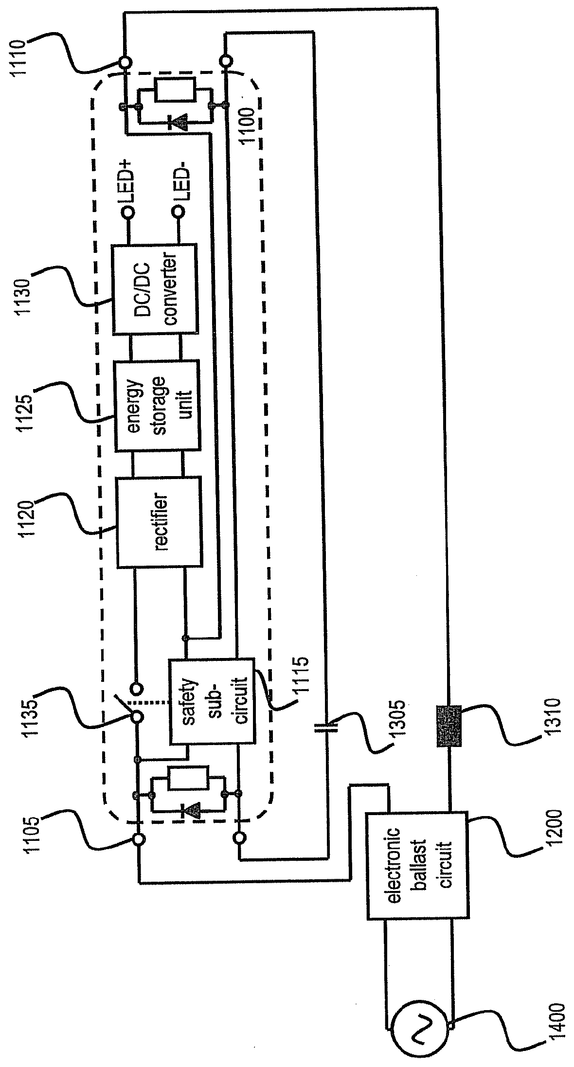
[0080]FIG. 1 shows a schematic view of a drive circuit for driving an LED array in connection with an electronic ballast circuit according to an exemplary embodiment of the invention. Drive circuit 1100 for driving an LED array is shown in connection with an electronic ballast circuit 1200. In particular, the drive circuit 1100 is connected to the electronic ballast circuit 1200 via two sets of terminals 1105 and 1110. A first set of terminals 1105 is connected to a first socket of a lighting device holder and the second set of terminals 1110 is connected to the second socket of the lighting device holder. Although not illustrated, the first and second socket of the lighting device holder are configured for receiving a fluorescent lighting device of e.g. the T5 or T8 type.

[0081]Each set of terminals 1105 and 1110 may include two terminals to be connected to each of the first and second socket of the lighting device holder. The first or second set of terminals may optionally also inc...


PUM


Abstract

The invention relates to a drive circuit for driving an LED array. In order to allow driving the LED array based on an AC current supplied by an electronic ballast circuit for driving a fluorescent lighting device, the invention provides for a power supply sub-circuit converting the supplied AC current to a DC current and at least partially storing energy of the converted DC current for driving the LED array. Further, the power supply sub-circuit is connected/disconnected to/from at least one of first or second terminals in response to the presence/absence of the AC current supplied via a terminal of at least one of the first or second terminals. Accordingly, the power supply sub-circuit is connected to the first and second terminals only when the supplied AC current is simultaneously supplied via a terminal of each of the first and second pair of terminals.

Description

FIELD OF THE INVENTION[0001]The invention relates to a drive circuit for driving a light-emitting diode (LED) array. The invention provides a drive circuit for driving an LED array based on an AC current supplied by an electronic ballast circuit for driving a fluorescent lighting device. The invention further relates to a LED lighting device comprising an LED array and a drive circuit and receiving an AC current from an externally housed electronic ballast circuit.TECHNICAL BACKGROUND[0002]Fluorescent lighting devices, also known as fluorescent lamps, are commonly used for illumination purposes. The most frequent type of a fluorescent lighting device is a hot cathode fluorescent lamp. In a hot cathode fluorescent lamp, combined filament / cathode units 10115, 10120 provide a high temperature so that an emitter substance (normally provided as a special coating) emits electrons to the gas-fill. The filament / cathode units 10115, 10120 are connected between each of the two sets of termina...

Claims


Application Information

Patent Timeline
IPC IPC(8): H05B37/02H05B44/00
CPCH05B33/0809Y02B20/386H05B33/0884Y02B20/30H05B45/382H05B45/3578H05B47/26H05B45/3725H05B31/50
Inventor ROEER, NORBERT
Owner ROEER NORBERT
Why Eureka
Try Eureka