
Ground fault detection circuit and ground fault detection apparatus

Inactive Publication Date: 2012-07-19
PANASONIC INTELLECTUAL PROPERTY MANAGEMENT CO LTD
View PDF4 Cites 18 Cited by
  • Summary
  • Abstract
  • Description
  • Claims
  • Application Information

AI Technical Summary

Benefits of technology

[0007]An advantage of the present invention is provision of a ground fault detection circuit and a ground fault detection apparatus that detect a ground fault.
is provision of a ground fault detection circuit and a ground fault detection apparatus that detect a ground fault.

Problems solved by technology

However, since a photoelectric conversion module that converts solar light to power does not have an electricity storage function, the module is used in combination with a secondary battery in some cases.

Method used


Image

  • Ground fault detection circuit and ground fault detection apparatus
  • Ground fault detection circuit and ground fault detection apparatus
  • Ground fault detection circuit and ground fault detection apparatus

Examples


first embodiment

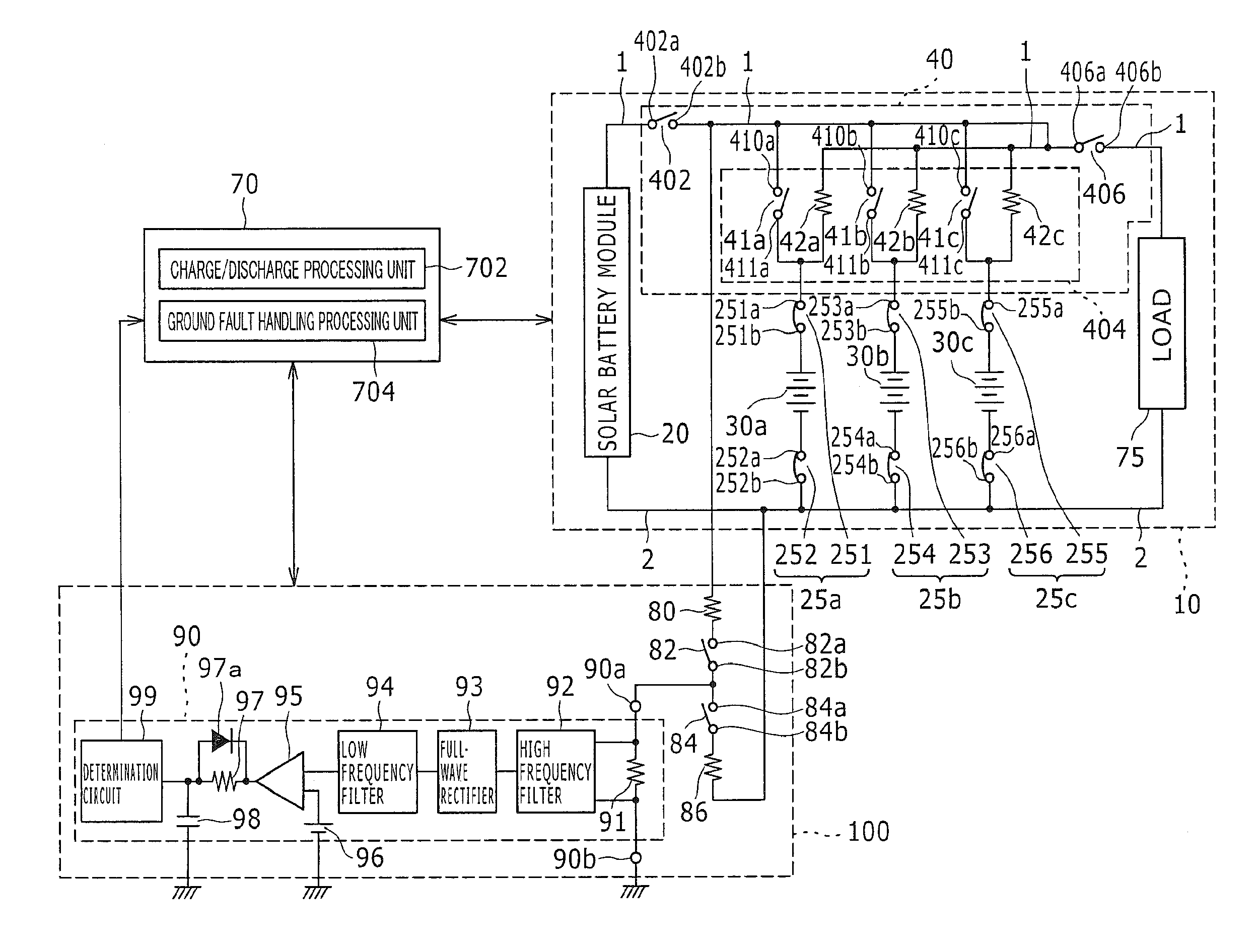
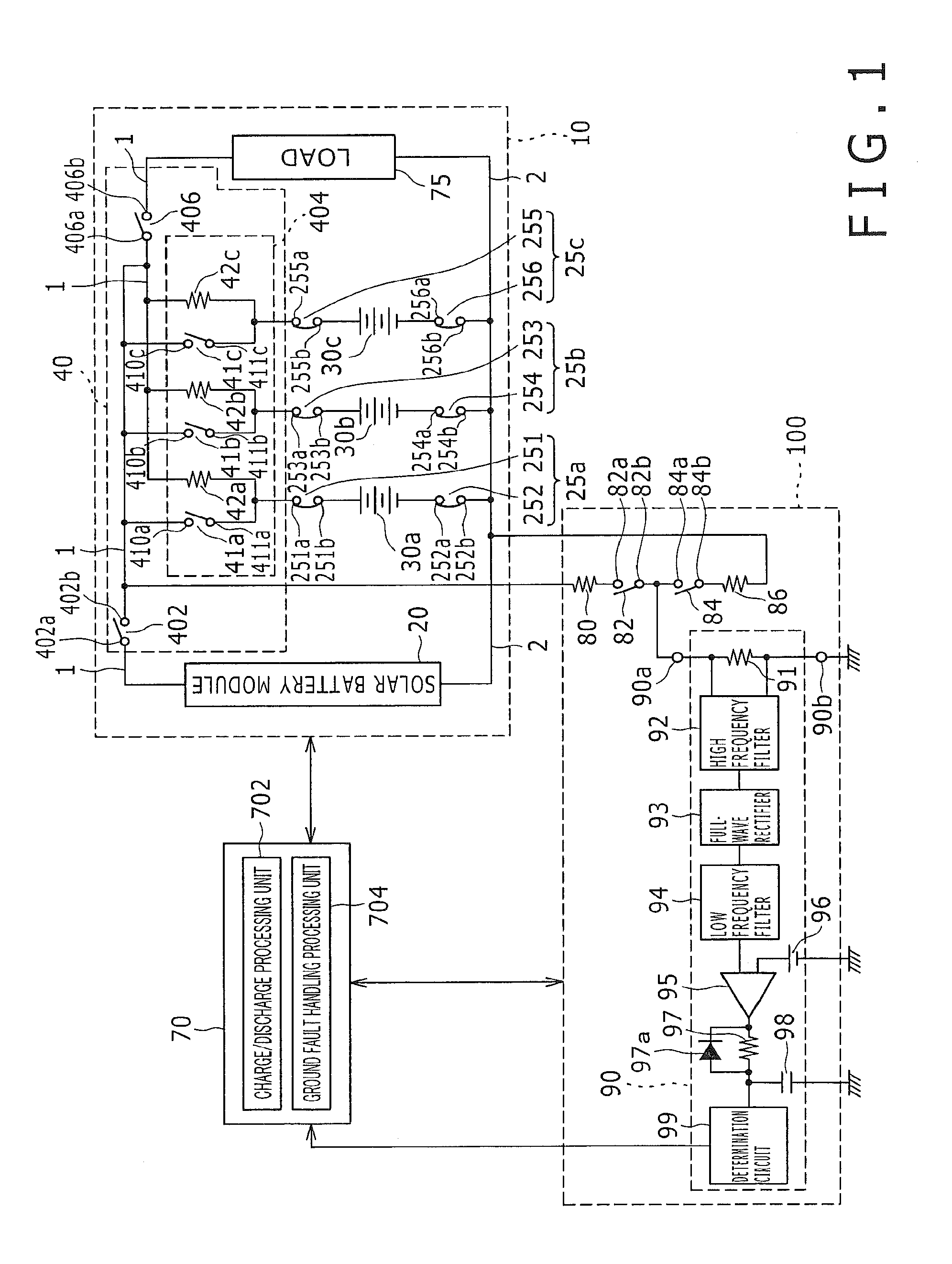
[0021]FIG. 1 is a view showing an electricity storage system 8. The electricity storage system 8 includes a ground fault detection circuit 100, a control unit 70, and a power supply system 10 for which the ground fault detection circuit 100 detects a ground fault. The power supply system 10 will be described first, and then the ground fault detection circuit 100 and the control unit 70 will be described. The electricity storage system 8 of FIG. 1 can include a ground fault detection apparatus. The ground fault detection apparatus included in the electricity storage system 8 includes at least the ground fault detection circuit 100 and a ground fault handling processing unit 704 as constituent elements and can further include other arbitrary components shown in FIG. 1 as constituent elements.

[0022]The power supply system 10 includes a solar battery module 20, breaker units 25a, 25b, and 25c, secondary battery units 30a, 30b, and 30c, a switch apparatus 40, and a load 75.

[0023]The sola...

second embodiment

[0074]FIG. 4 is a schematic configuration diagram of an electricity storage system 9. The electricity storage system 9 includes all or part of the components shown in FIG. 4. The electricity storage system 9 of FIG. 4 corresponds to the electricity storage system 8 of FIG. 1. For example, a power block PB1, a power block PB2, a charge switch circuit 21, a discharge switch circuit 22, a ground fault detection circuit 29, and a ground fault detection control unit 39 in FIG. 4 can correspond to the solar battery module 20, the load 75, the charge switch circuit 402, the discharge switch circuit 406, the ground fault detection circuit 100, and the ground fault handling processing unit 704 in FIG. 1, respectively. Description of elements similar to those of the first embodiment will be omitted as necessary.

[0075]A secondary battery unit 11 includes one or more secondary batteries that store power. The secondary batteries forming the secondary battery unit 11 are secondary batteries of an...


PUM


Abstract

A ground fault detection circuit includes: a first switch circuit that connects / disconnects a first path between a positive bus bar and a ground potential section, the positive bus bar being connected to positive electrodes of secondary battery units through a field-effect transistor including a parasitic diode; a second switch circuit that connects / disconnects a second path between a negative bus bar and a ground potential section, the negative bus bar being connected to negative electrodes of the secondary battery units; and a ground fault detection unit that detects a ground fault of the positive bus bar or the negative bus bar based on an electric current flowing through the first path or the second path.

Description

CROSS-REFERENCE TO RELATED APPLICATION[0001]The present application is a continuation application of International Application No. PCT / JP2011 / 072340, filed Sep. 29, 2011, the entire contents of which are incorporated herein by reference and priority to which is hereby claimed. The PCT / JP2011 / 072340 application claimed the benefit of the date of the earlier filed Japanese Patent Application Nos. JP2010-228822, filed Oct. 8, 2010, and JP2011-174698, filed Aug. 10, 2011, the entire contents of which are incorporated herein by reference, and priority to which is hereby claimed.TECHNICAL FIELD[0002]The present invention generally relates to a ground fault detection circuit and a ground fault detection apparatus, and more particularly to a ground fault detection circuit and a ground fault detection apparatus that detect a ground fault of a positive bus bar or a negative bus bar.[0003]An electricity storage device, such as a secondary battery, is used to use energy efficiently. For example...

Claims


Application Information

Patent Timeline
IPC IPC(8): G01R31/14
CPCG01R31/025H02H7/20H02H3/16G01R31/52
Inventor IKE, TAKEHITOABE, TAKAYOSHINAKAI, TOMOMICHINAKASHIMA, TAKESHIISHIMOTO, KAZUO
Owner PANASONIC INTELLECTUAL PROPERTY MANAGEMENT CO LTD
Learn More