Light-emitting diode lampshade

a technology of light-emitting diodes and lampshades, which is applied in the field of lampshades, can solve the problems of lampshades that fail to meet the market demand, the luminance is dimmed, and the light concentration performance is affected, so as to achieve enhanced light transmittance and concentration

Inactive Publication Date: 2012-07-19
DBM REFLEX TAIWAN
View PDF12 Cites 78 Cited by
  • Summary
  • Abstract
  • Description
  • Claims
  • Application Information

AI Technical Summary

Benefits of technology

[0006]An objective of the present invention is to provide an LED lampshade having a shorter distance between a light incident portion and a light emitting portion, and enhanced light transmittance and concentration therethrough.

Problems solved by technology

However, as light emitted by LEDs must be refracted by the light concentration wall and transmitted through the light emitting surface of the lampshade, and the distance between the recess and the light emitting surface is quite far, the light concentration performance is affected and luminance is dimmed.
As a consequence, such a lampshade fails to satisfy the market demand.

Method used


Image

  • Light-emitting diode lampshade
  • Light-emitting diode lampshade
  • Light-emitting diode lampshade

Examples


first embodiment

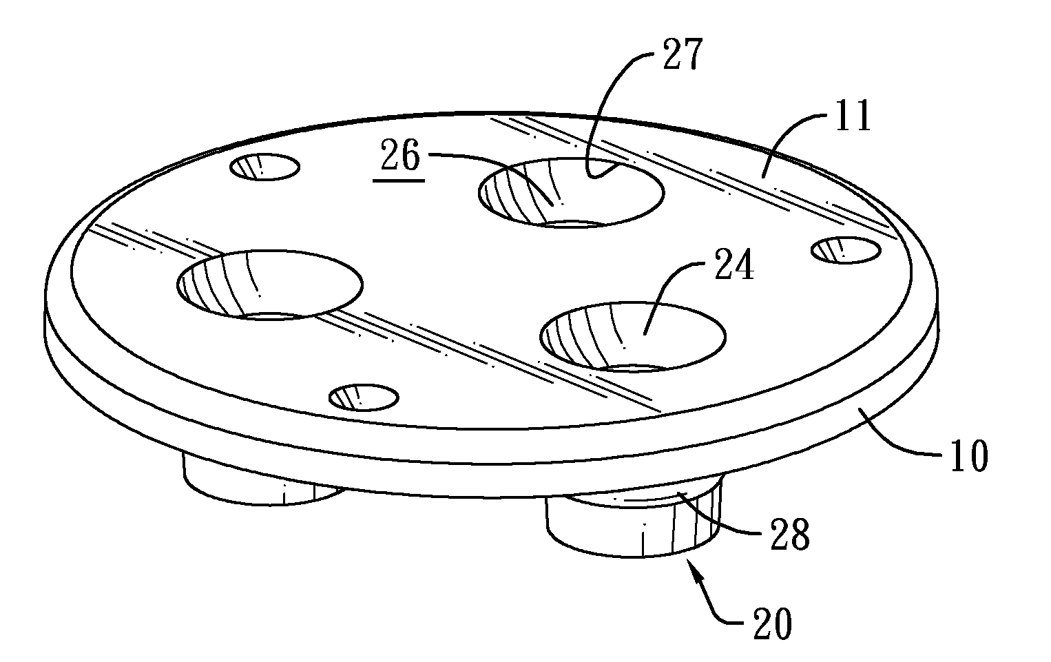
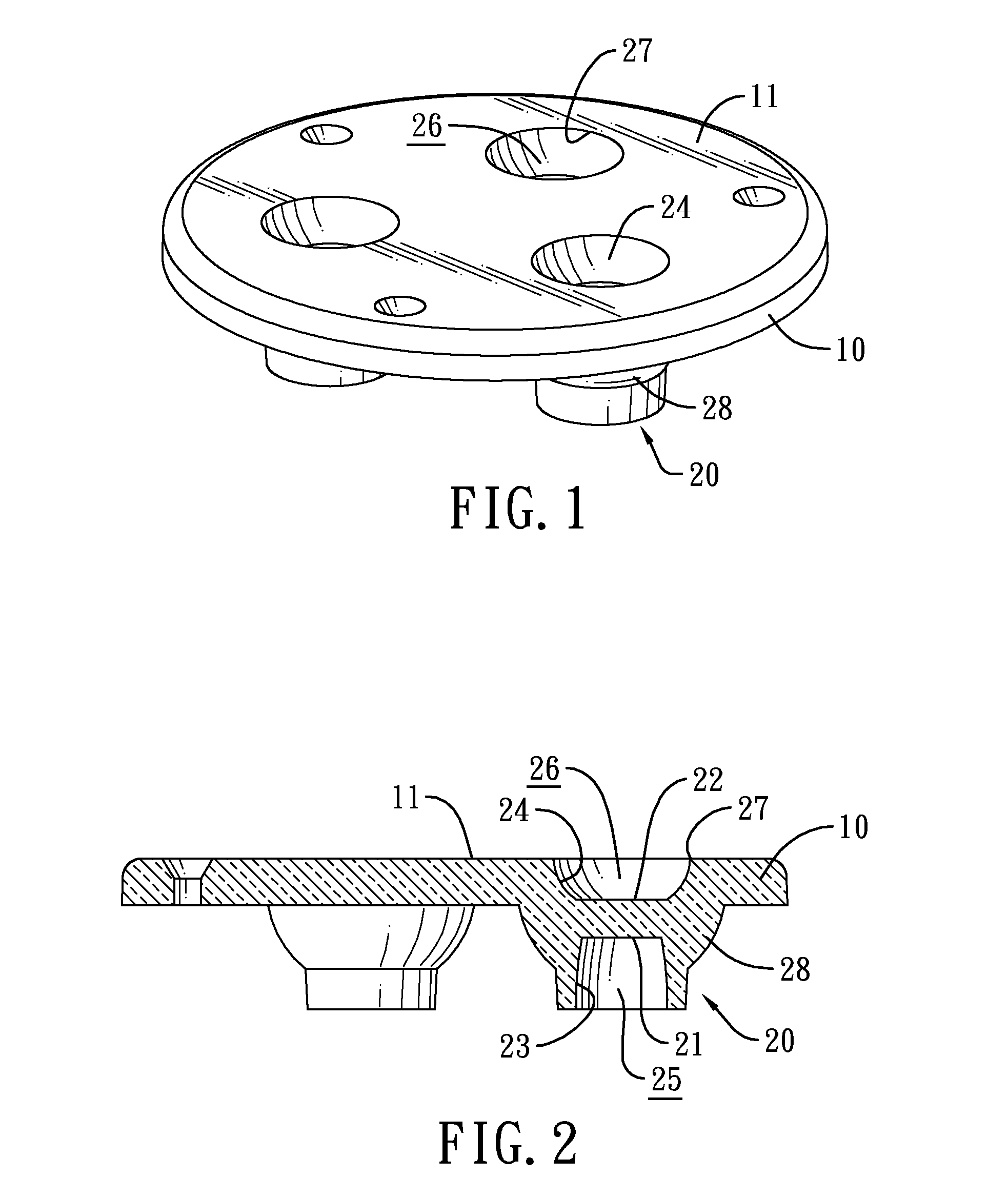
[0025]With reference to FIGS. 1 and 2, a light-emitting diode (LED) lampshade in accordance with the present invention has a body 10 and multiple light concentrators 20.

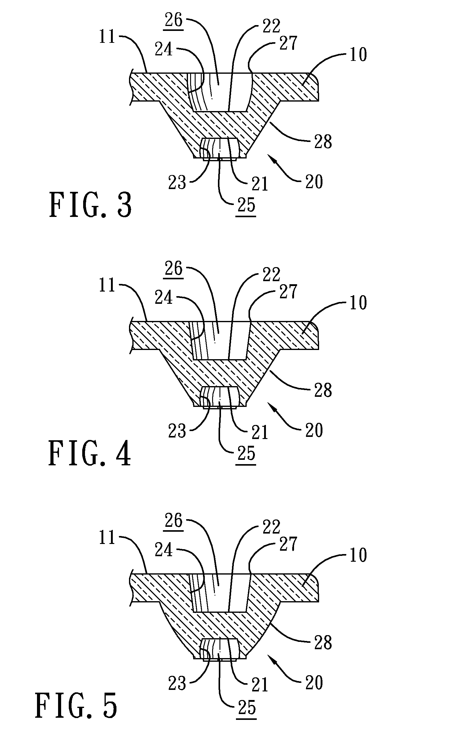
[0026]The body 10 has a light exit plane 11 formed on a top of the body 10. The light concentrators 20 are formed on the body 10, and each light concentrator 20 has a light incident recess 21 and a light transmitting recess 22. The light incident recess 21 has a first concentration wall 23 and a first chamber 25 defined by the first concentration wall 23. The light transmitting recess 22 corresponds to the light incident recess 21, and has a second concentration wall 24, a second chamber 26 and an opening 27. The second chamber 26 is defined by the second concentration wall 24 and oppositely facing the first chamber 25. The opening 27 is formed through the light exit plane 11. Each light concentrator 20 further has an third concentration wall 28 formed around a periphery of the light concentrator 20.

[0027]With refere...

ninth embodiment

[0028]With reference to FIGS. 10 and 11, an LED lampshade in accordance with the present invention is shown. The body 10 may have three, five, seven or other numbers of light concentrators 20, and the body may further have a plurality of ribs 12 juxtaposedly formed on a periphery of a sidewall of the body.

tenth embodiment

[0029]With reference to FIGS. 12 and 13, an LED lampshade in accordance with the present invention is shown. The body 10 further has a concentrated light area 13 and a uniform light area 14. The concentrated light area 13 is adjacent to the openings 27. The uniform light area 14 has a plurality of bumps 15 formed thereon. The lampshade is mounted to cover a lamp holder 30. An LED module 40 of an LED lamp is mounted between the lampshade and the lamp holder 30, and has a circuit board 41. The circuit board 41 has multiple LEDs 42 mounted thereon.

[0030]Each light concentrator 20 of the LED lampshade corresponds to and aligns with one of the LEDs 42 of the LED module 40. An emitting end of each LED 42 is inserted in the first chamber 25 of a corresponding light concentrator 20. Light emitted from the LED 42 can be emitted through the exit plane 11 of the body 10 of the LED lampshade through the following paths. Light emitted from the LED 42 is first reflected or refracted by the first ...


PUM


Abstract

An LED lampshade has a body and multiple light concentrators. The body has a light exit plane. The light concentrators are formed on the body. Each light concentrator has a light incident recess, a light transmitting recess and an third concentration wall. The light incident recess has a first concentration wall and a first chamber defined by the first concentration wall. The light transmitting recess corresponds to the light incident recess, and has a second concentration wall, a second chamber defined by the second concentration wall and opposite to the first chamber, and an opening formed through the light exit plane. The third concentration wall is formed around a periphery of the light concentrator. Given the opposite light incident recess and light transmitting recess and the three concentration walls, the LED lampshade enhances light transmittance and concentration therethrough.

Description

BACKGROUND OF THE INVENTION[0001]1. Field of the Invention[0002]The present invention relates to a lampshade, and more particularly to a light-emitting diode (LED) lampshade having a shorter distance between a light incident portion and a light emitting portion, and enhanced light transmittance and concentration through the lampshade.[0003]2. Description of the Related Art[0004]A conventional LED lamp normally has a base, an LED module and a lampshade. The LED module is mounted on the base, and has a circuit board having LEDs mounted thereon. The lampshade is mounted on and covers the base, and has a body. The body has a light incident surface and a light emitting surface. The light incident surface is adjacent to the LEDs, and has multiple recesses. The recess is formed in the light incident surface, faces the LEDs, and has a circular light concentration wall inside the recess to define a chamber to hold a corresponding LED inside. The light emitting surface is a plane.[0005]Howeve...

Claims


Application Information

Patent Timeline
Patent Type & Authority Applications(United States)
IPC IPC(8): F21V11/00
CPCF21V5/007F21V5/04F21Y2105/001F21Y2101/02F21V7/0091F21Y2105/10F21Y2115/10
Inventor CHOU, MIN-HWA
Owner DBM REFLEX TAIWAN
Why Eureka
Try Eureka