Seal system for cooling fluid flow through a rotor assembly in a gas turbine engine

a gas turbine engine and cooling fluid technology, applied in the field of turbine engines, can solve the problems of pressure loss and restrict and achieve the effect of enhancing the flow of cooling fluid

Inactive Publication Date: 2012-07-19
SIEMENS ENERGY INC
View PDF24 Cites 2 Cited by
  • Summary
  • Abstract
  • Description
  • Claims
  • Application Information

AI Technical Summary

Benefits of technology

[0004]This invention is directed to a sealing system for a rotor assembly in a gas turbine engine that enhances the flow of cooling fluids from a rotor assembly to turbine blades. The sealing system may include a seal configured to seal a conduit directing cooling fluids from a cooling fluid source into turbine blades attached to the rotor assembly. In one embodiment, the seal may be formed from a side block and an upper seal that seal a gap between a radially outward extending first rotor supply channel in the rotor assembly terminating at an inlet of an axially extending second rotor supply channel that is in fluid communication with an internal blade cooling system of a turbine blade. The seal may include components that enhance the flow of cooling fluids over conventional configurations. In another embodiment, the sealing system may include an integrated sealing block configured to seal the gap between adjacent turbine blades at an intersection between the first and second rotor supply channels. The integrated sealing block may be formed from a radially inward extending leg and a central body.

Problems solved by technology

Turbine blades, vanes and other components often contain cooling systems for prolonging the life of these items and reducing the likelihood of failure as a result of excessive temperatures.
Conventional cooling channels in the rotor assembly often have cooling fluid leaks between radially extending and axially extending cooling channels that direct cooling fluids to turbine vanes.
Additionally, conventional cooling fluid supply configurations often have choke points that cause pressure losses and unduly restrict cooling fluid flow.

Method used


Image

  • Seal system for cooling fluid flow through a rotor assembly in a gas turbine engine
  • Seal system for cooling fluid flow through a rotor assembly in a gas turbine engine
  • Seal system for cooling fluid flow through a rotor assembly in a gas turbine engine

Examples


Embodiment Construction

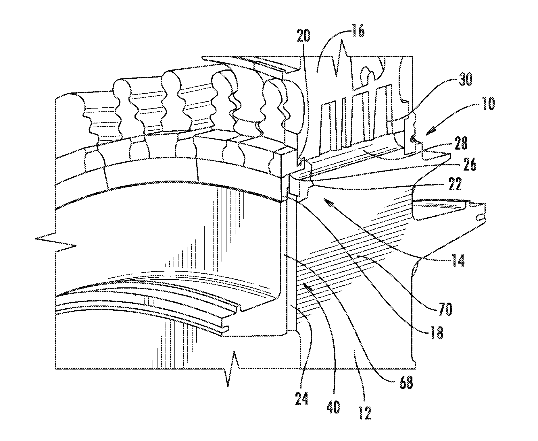
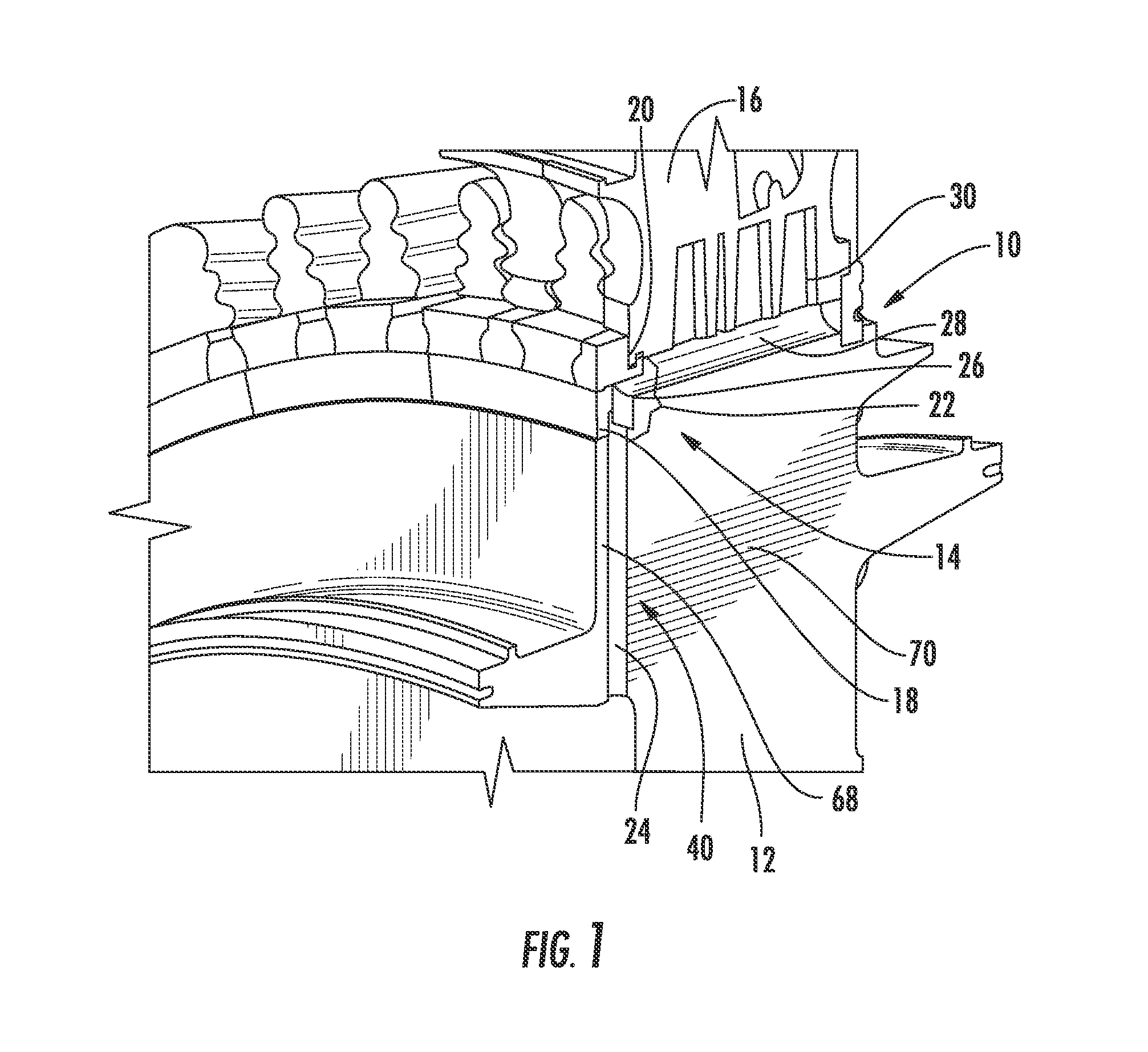
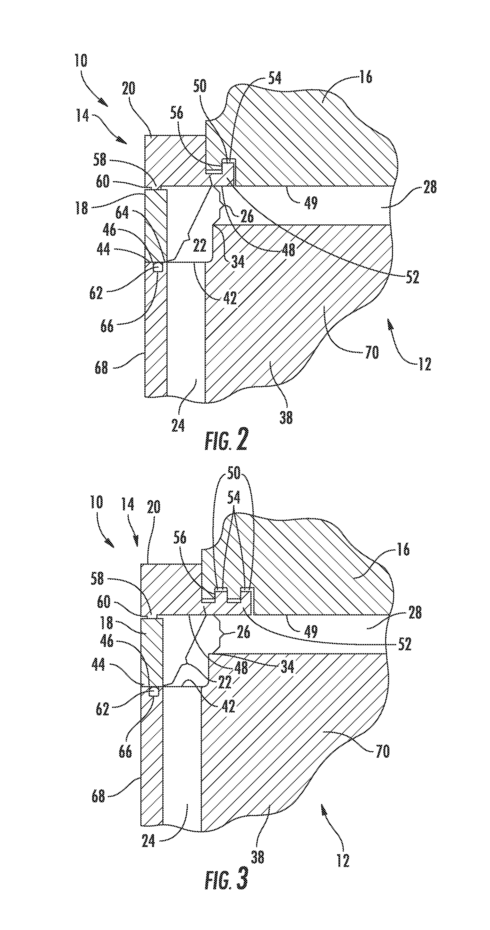
[0023]As shown in FIGS. 1-5, this invention is directed to a sealing system 10 for a rotor assembly 12 in a gas turbine engine that enhances the flow of cooling fluids from a rotor assembly 12 to turbine blades 16. The sealing system 10 may include a seal 14 configured to seal a conduit directing cooling fluids from a cooling fluid source into turbine blades 16 attached to the rotor assembly 12. In one embodiment, the seal 14 may be formed from a side block 18 and an upper seal 20 that seal a gap 22 between a radially outward extending first rotor supply channel 24 in the rotor assembly 12 terminating at an inlet 26 of an axially extending second rotor supply channel 28 that is in fluid communication with an internal blade cooling system 30 of a turbine blade 16. The seal 14 may include components that enhance the flow of cooling fluids over conventional configurations. In another embodiment, the sealing system 10 may include an integrated sealing block 32 configured to seal the gap...


PUM


Abstract

A sealing system for a rotor assembly in a gas turbine engine is disclosed. The sealing system may include a seal formed from a side block and an upper seal that seals a gap between a radially outward extending first rotor supply channel in a rotor assembly terminating at an inlet of an axially extending second rotor supply channel that is in fluid communication with an internal blade cooling system of a turbine blade. The seal may include components that enhance the flow of cooling fluids over conventional configurations. In another embodiment, the sealing system may include an integrated sealing block configured to seal a gap between adjacent turbine blades at an intersection between the first and second rotor supply channels. The integrated sealing block may be formed from a radially inward extending leg and central body.

Description

FIELD OF THE INVENTION[0001]This invention is directed generally to turbine engines, and more particularly to cooling fluid feed systems in turbine engines.BACKGROUND[0002]Typically, gas turbine engines include a compressor for compressing air, a combustor for mixing the compressed air with fuel and igniting the mixture, and a turbine blade assembly for producing power. Combustors often operate at high temperatures that may exceed 2,500 degrees Fahrenheit. Typical turbine combustor configurations expose turbine blade assemblies to these high temperatures. As a result, turbine blades and turbine vanes must be made of materials capable of withstanding such high temperatures. Turbine blades, vanes and other components often contain cooling systems for prolonging the life of these items and reducing the likelihood of failure as a result of excessive temperatures.[0003]Turbine blades are typically supported by a rotor assembly that enables turbine blades to extend radially outward circum...

Claims


Application Information

Patent Timeline
Patent Type & Authority Applications(United States)
IPC IPC(8): F01D5/18
CPCF01D5/3015
Inventor MHETRAS, SHANTANU P.SHIVANAND, MANJITCHEHAB, ABDULLATIF M.LEE, CHING-PANG
Owner SIEMENS ENERGY INC
Why Eureka
Try Eureka