Method and arrangement for measuring at least one physical magnitude, such as temperature, flow or pressure of the cooling fluid flowing in an individual cooling element cycle of a cooling element in a metallurgical furnace

a technology of cooling element and measurement method, which is applied in the direction of heat measurement, instruments, furnaces, etc., can solve the problems of unbalanced temperature distribution, inability to measure, and inability to accurately measure, so as to increase the flow of cooling fluid, prevent damage, and slow down the wear of cooling elements

Active Publication Date: 2010-12-30
METSO OUTOTEC (FINLAND) OY
View PDF6 Cites 2 Cited by
  • Summary
  • Abstract
  • Description
  • Claims
  • Application Information

AI Technical Summary

Benefits of technology

[0017]The wearing of the cooling elements can be slowed down, and the damaging thereof prevented, because information is obtained on the cooling element level, and cooling can be boosted in those locations, i.e. cooling elements, where the thermal stress is high, by increasing the flow of the cooling fluid. Because information is obtained on the cooling element level, a solution according to the invention makes it easier to anticipate problematic situations and enhances a safe operation and usage of the metallurgical furnace.
[0018]Because information is obtained on the cooling element level, water consumption can be optimized by focusing and / or by increasing the flow of the cooling fluid in those cooling elements where more cooling is needed, and it is not necessary to increase the flow of the cooling fluid in the whole system between the supply header and the collection header.
[0019]Another advantage is also achieved by means of the solution according to the invention. It is known that a high temperature in a cooling element vaporizes the cooling fluid in the cooling element cycle of a cooling element, and as a consequence, there is created vapor in the cooling element cycle of the cooling element, which vapor prevents the cooling fluid from flowing through the cooling element in the cooling element cycle, and as a result, the cooling element looses its cooling capacity. The loss of the cooling capacity can finally lead to the destruction of the cooling element in question, and it may be necessary to interrupt the whole process in the metallurgical furnace in order to replace the damaged element. In the solution according to the invention, such weakened cooling elements can be detected in good time, and the flow of the cooling fluid can be increased in order to prevent the formation of a so-called vapor lock.
[0020]In addition to technical advantages, the invention also improves cost efficiency. The flow of the cooling fluid can be more accurately focused on the appropriate spots, and therefore the refractory lining structure of the metallurgical furnace wears better, which again results in fewer maintenance interruptions. Because the flow of the cooling fluid can be more accurately focused on the appropriate spots, the measures of the metallurgical furnace can be designed more precisely, i.e. unnecessary sizing allowances can be avoided. And further, because the flow of the cooling fluid can be more accurately focused on the appropriate spots, the solution according to the invention consumes less cooling fluid, which correspondingly results in a reduced cooling need for heated cooling fluid.

Problems solved by technology

Owing to the combined effect of these stresses, an unbalanced temperature distribution is formed in the refractory lining structure, which phenomenon is undesirable for the total durability of the lining.
Before manipulating the rates of flow, it is necessary to know the heat loss of each cooling element, but earlier the measuring thereof has been very expensive owing to the fact that each cooling element cycle has been provided with a an individual meter and cabling.
The adding of a heat and flow meter in every cycle is, however, unnecessary, because the momentary return temperature and flow rate of each cooling element in the cycle does not represent very vital information for the process control.

Method used


Image

  • Method and arrangement for measuring at least one physical magnitude, such as temperature, flow or pressure of the cooling fluid flowing in an individual cooling element cycle of a cooling element in a metallurgical furnace
  • Method and arrangement for measuring at least one physical magnitude, such as temperature, flow or pressure of the cooling fluid flowing in an individual cooling element cycle of a cooling element in a metallurgical furnace
  • Method and arrangement for measuring at least one physical magnitude, such as temperature, flow or pressure of the cooling fluid flowing in an individual cooling element cycle of a cooling element in a metallurgical furnace

Examples


Embodiment Construction

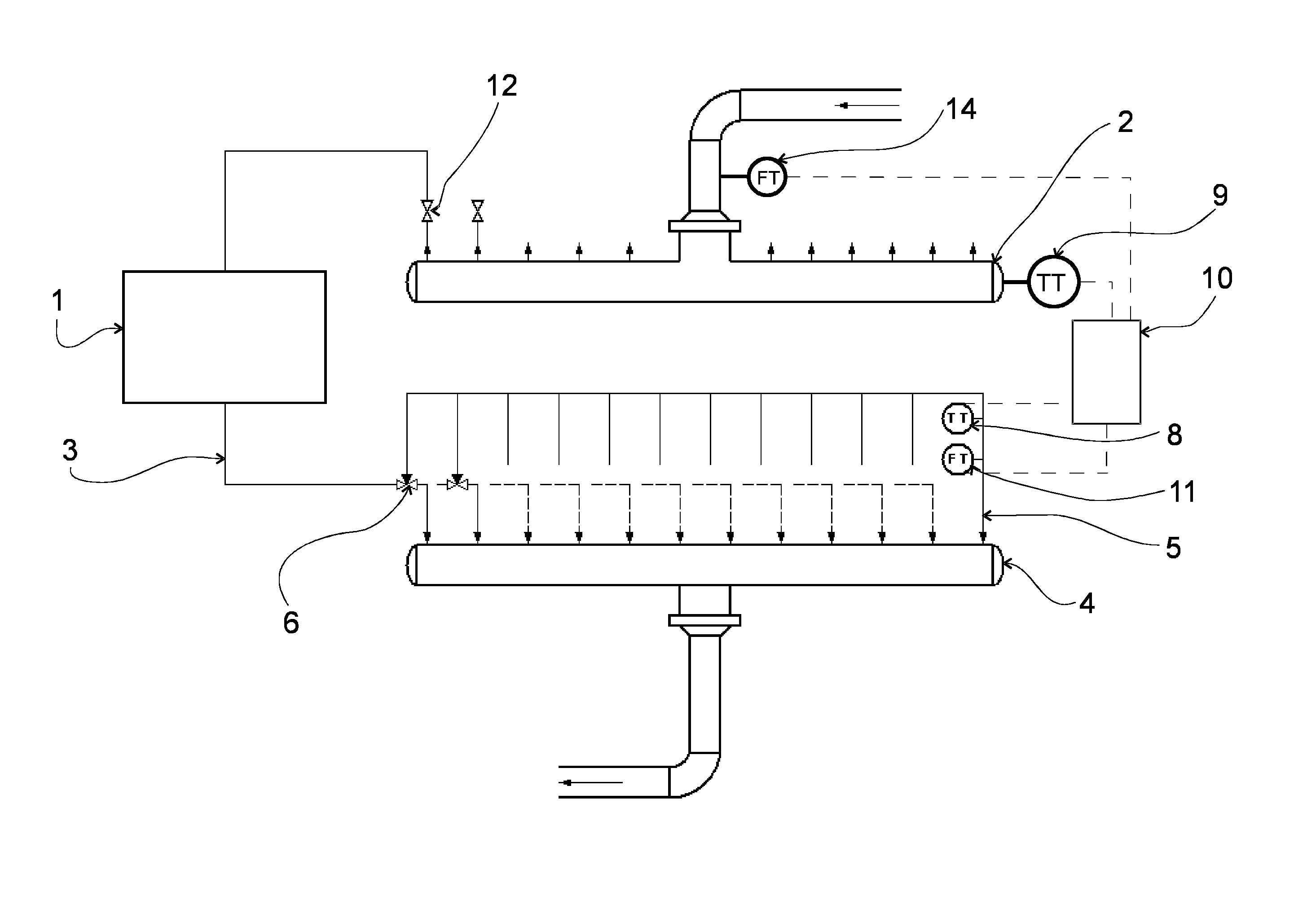
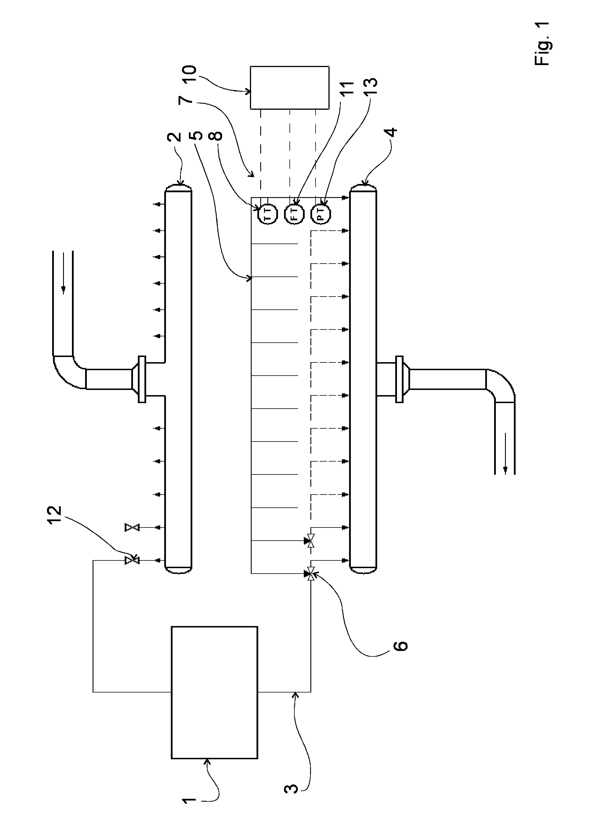
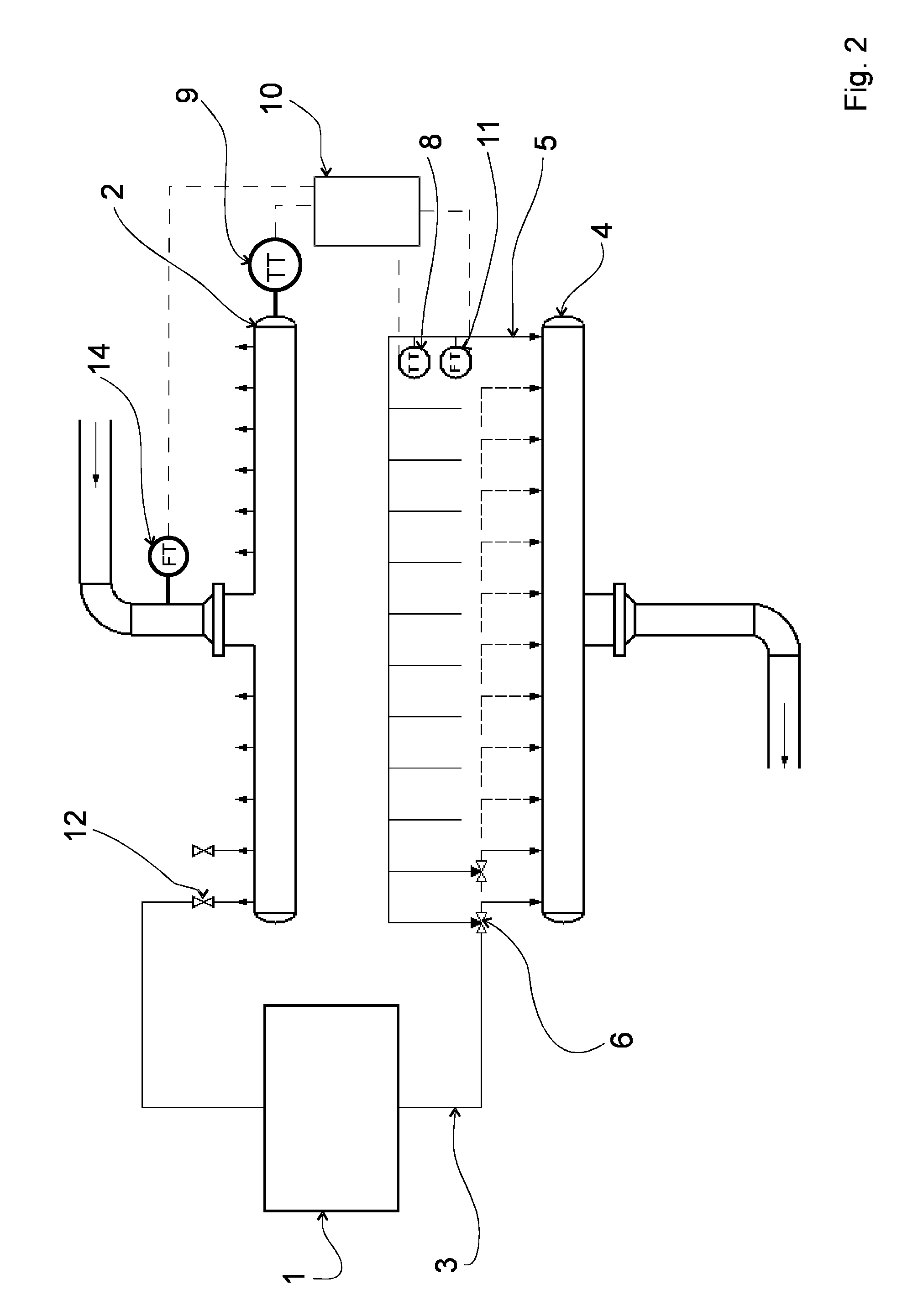
[0025]The drawings illustrate an arrangement for measuring at least one physical magnitude such as temperature, flow or pressure of the cooling fluid flowing in an individual cooling element cycle 3 of a cooling element 1 in a metallurgical furnace (not illustrated in the drawings).

[0026]The arrangement comprises a supply header 2 for distributing and feeding cooling fluid (not illustrated in the drawings) in the cooling element cycles 3 of cooling elements 1. The cooling fluid is for example water.

[0027]The arrangement also comprises a collection header 4 for collecting and receiving cooling fluid from the cooling element cycles 3 of the cooling elements 1.

[0028]In addition, the arrangement comprises a survey line 5, which is by intermediation of a valve arrangement 6 in fluid connection with at least one cooling element cycle 3, so that cooling fluid is conducted alternatively through the survey line 5 to the collection header 4 or past the survey line 5 to the collection header 4...


PUM

PropertyMeasurementUnit
temperatureaaaaaaaaaa
pressureaaaaaaaaaa
physical magnitudeaaaaaaaaaa

Abstract

The invention relates to a method and arrangement for measuring at least one physical magnitude, such as temperature, flow or pressure of the cooling fluid flowing in an individual cooling element cycle (3) of a cooling element (1) in a metallurgical furnace. The arrangement includes a supply header (2) for distributing the cooling fluid and for feeding it to the cooling element cycles (3) of the cooling elements (1), and a collection header (4) for collecting and receiving cooling fluid from the cooling element cycles (3) of the cooling elements (1). The arrangement includes a survey line (5) that is by intermediation of a valve arrangement (6) in fluid connection with at least one cooling element cycle (3), so that the cooling fluid is conducted alternatively through the survey line (5) to the collection header (4) or past the survey line (5) to the collection header (4). The survey line (5) comprises at least one measuring device (7) for measuring at least one physical magnitude of the cooling fluid flowing in the survey line (5), and for measuring the cooling element cycle (3).

Description

BACKGROUND OF THE INVENTION[0001]The invention relates to a method according to the preamble of claim 1 for measuring at least one physical magnitude, such as temperature, flow or pressure of the cooling fluid flowing in an individual cooling element cycle of a cooling element in a metallurgical furnace.[0002]The invention also relates to an arrangement according to the preamble of claim 11 for measuring at least one physical magnitude, such as temperature, flow or pressure of the cooling fluid flowing in an individual cooling element cycle of a cooling element in a metallurgical furnace.[0003]The invention deals with cooling in a liquid metallurgical process, in a metallurgical furnace such as a suspension smelting furnace, for example a flash smelting furnace, by a cooling system including several supply headers for distributing cooling fluid, such as cooling water, to the cooling element cycles of the cooling elements used for cooling a metallurgical furnace, said system also inc...

Claims


Application Information

Patent Timeline
Patent Type & Authority Applications(United States)
IPC IPC(8): G01K13/00G01N3/60G01F7/00G01F1/00G01L7/00G01K13/02
CPCC21B7/10C21B7/24G01K13/02F27D19/00F27D21/00F27D9/00
Inventor SAARINEN, RISTOPESONEN, LAURI
Owner METSO OUTOTEC (FINLAND) OY
Why Eureka
Try Eureka