Method for Controlling Injection Amount of Fuel of Burner and Aftertreating Device of Exhaust Gas

Inactive Publication Date: 2012-07-26
SK INNOVATION CO LTD
View PDF1 Cites 4 Cited by
  • Summary
  • Abstract
  • Description
  • Claims
  • Application Information

AI Technical Summary

Benefits of technology

[0027]According to the method for controlling the injection amount of fuel of the burner and the aftertreating device of exhaust gas according to the present invention as described above, there is provided a sensor for controlling the fuel injection amount of the burner in consideration of the exothermic effect occurred when the fuel injected from the burner p

Problems solved by technology

But the temperature of the exhaust gas after passing through the catalytic filter or the pro-catalyst may be 900° C. between the catalytic filter and the pro-catalyst or at

Method used


Image

  • Method for Controlling Injection Amount of Fuel of Burner and Aftertreating Device of Exhaust Gas
  • Method for Controlling Injection Amount of Fuel of Burner and Aftertreating Device of Exhaust Gas
  • Method for Controlling Injection Amount of Fuel of Burner and Aftertreating Device of Exhaust Gas

Examples


Example

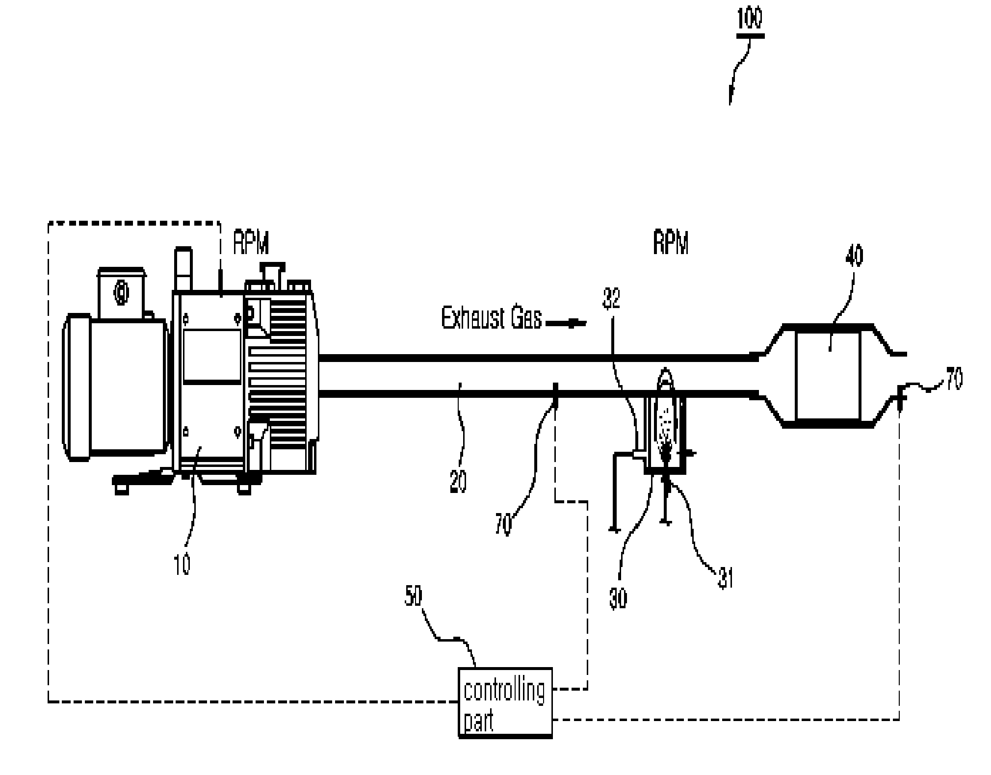
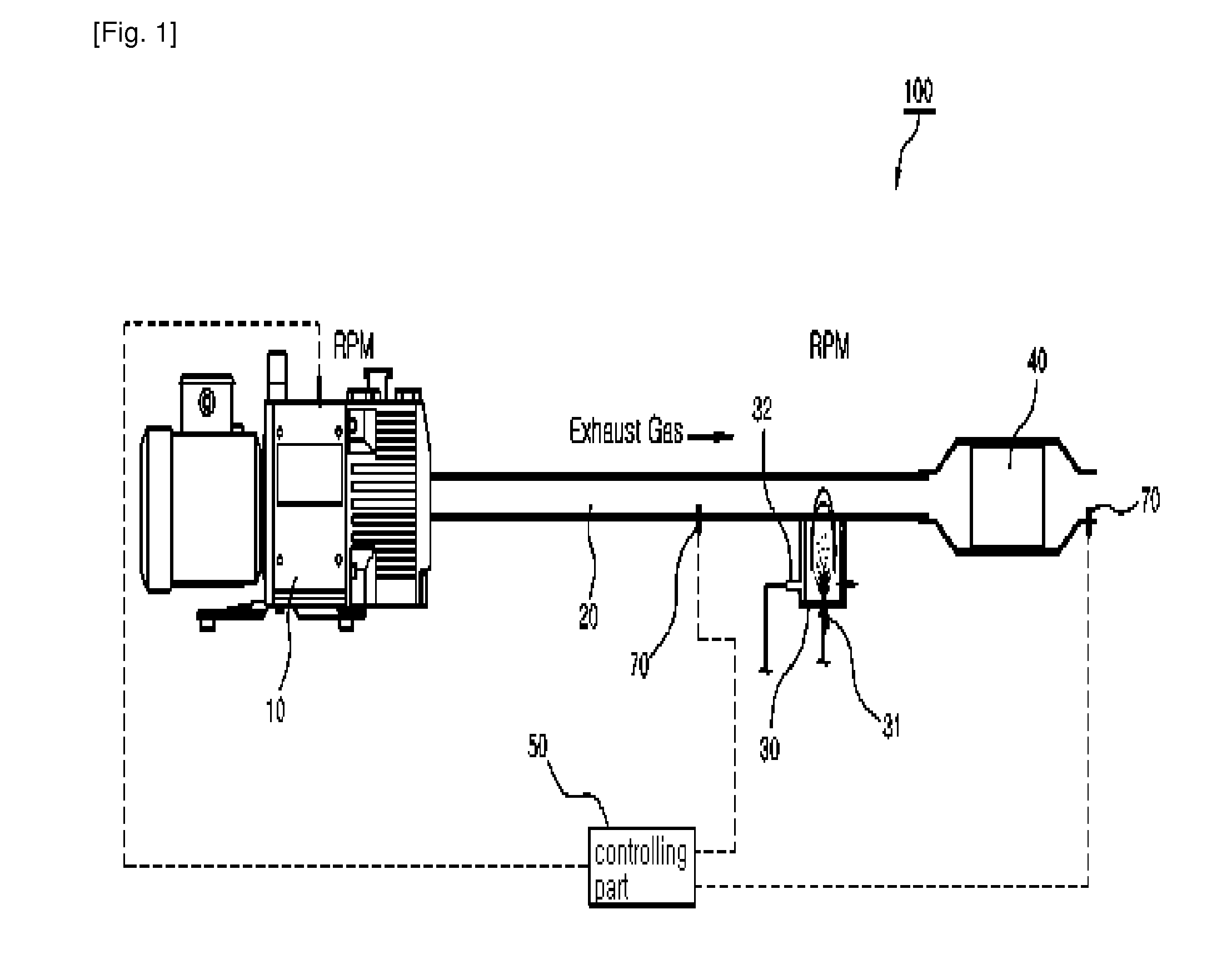
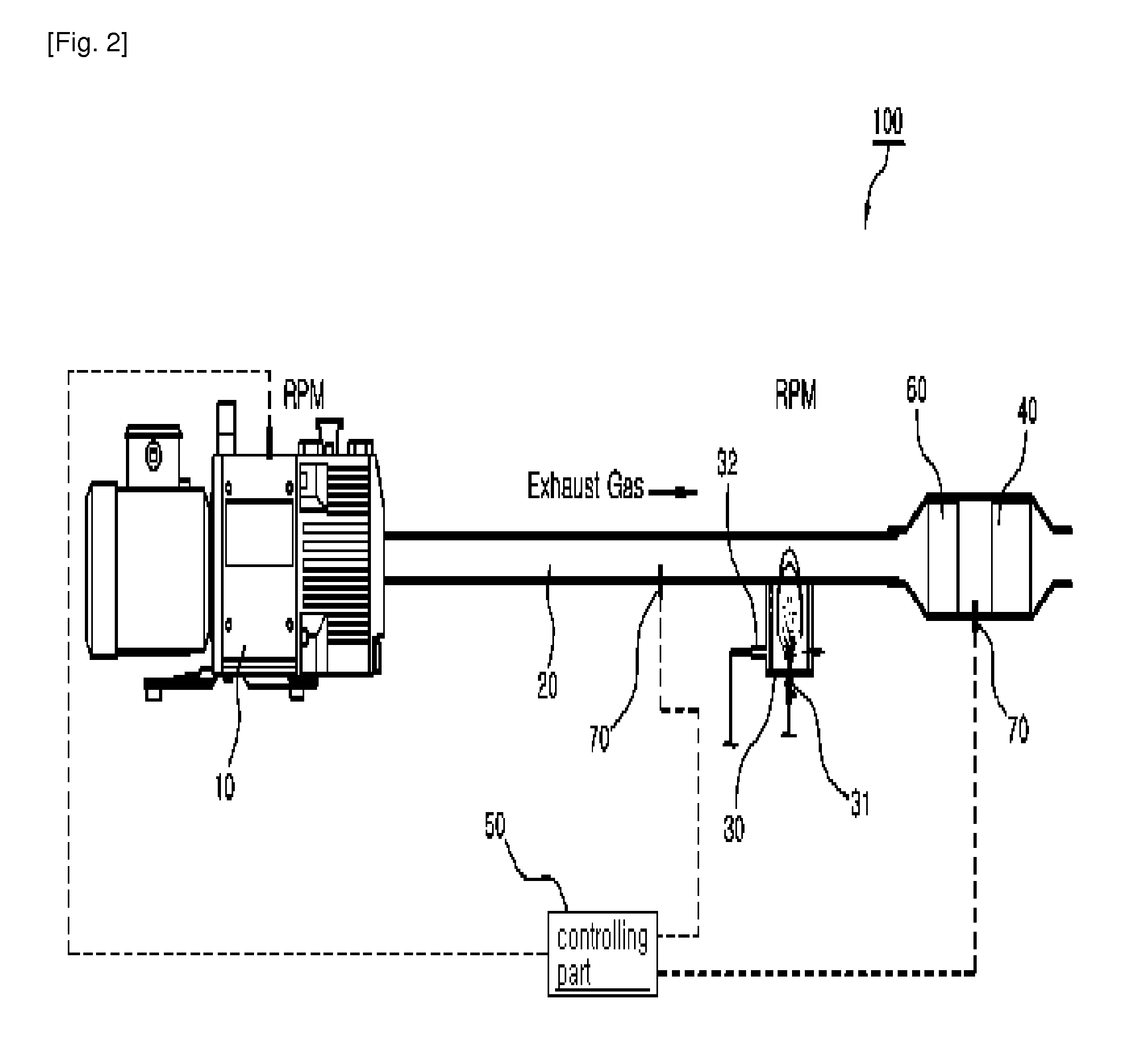
[0033]10: engine[0034]20: vent pipe[0035]30: burner[0036]31: fuel injecting part[0037]32: igniting means[0038]40: catalytic filter[0039]50: controlling part[0040]60: pro-catalyst[0041]100: aftertreating device of exhaust gas

BEST MODE FOR CARRYING OUT THE INVENTION

[0042]Hereinafter, the embodiments of the present invention will be described in detail with reference to accompanying drawings.

[0043]FIGS. 1 and 2 are views of an aftertreating device 100 of exhaust gas in accordance with each embodiment of the present invention.

[0044]The aftertreating device 100 of exhaust gas of the present invention includes a burner 30 which is disposed at a vent pipe 20, a catalytic filter 40, a temperature sensor 70 and a controlling part 50.

[0045]The aftertreating device 100 of exhaust gas of the present invention is disposed at the vent pipe 20 through which the exhaust gas generated from a diesel engine 10 is flowed.

[0046]The burner 30 includes a fuel injecting part 31 and an igniting means 32 so ...


PUM


Abstract

Disclosed is a method for controlling an injection amount of fuel of a burner and an aftertreating device of exhaust gas, and more particularly, to a method for controlling an injection amount of fuel of a burner and an aftertreating device of exhaust gas, in which the burner is controlled in consideration of exothermic effect due to a catalytic filter, thereby stably reducing exhaust gas.

Description

TECHNICAL FIELD[0001]The present invention relates to a method for controlling an injection amount of fuel of a burner and an aftertreating device of exhaust gas, and more particularly, to a method for controlling an injection amount of fuel of a burner and an aftertreating device of exhaust gas, in which the burner is controlled in consideration of exothermic effect due to a catalytic filter, thereby stably reducing exhaust gas.BACKGROUND ART[0002]In general, since a diesel engine has higher power and lower fuel expenses than a gasoline engine, it is widely applied to vehicles, construction equipments, ships and the like.[0003]However, the diesel engine is a four-stroke engine in which fuel is injected into the engine and then burnt in a compression ignition method, and in a self-ignition process of the fuel, incomplete combustion occurs due to non-uniformity of a fuel-air ratio, and thus noxious particle (exhaust gas) is generated.[0004]Particularly, the noxious particle mainly co...

Claims


Application Information

Patent Timeline
IPC IPC(8): F01N3/025
CPCF01N3/0253F01N3/2033Y02T10/47Y02T10/26F01N9/00Y02T10/12Y02T10/40F01N3/025
Inventor KIM, YOUNGSHOLKIM, YONGWOOYOU, KUNCHONGSEO, MYEONG SOOKIM, SUNGHWANJUNG, HONGSEOKKIM, YUNSIK
Owner SK INNOVATION CO LTD
Why Eureka
Try Eureka