
Particulate filter and associated methods for exhaust purification

Inactive Publication Date: 2012-11-22
FORD GLOBAL TECH LLC
View PDF15 Cites 2 Cited by
  • Summary
  • Abstract
  • Description
  • Claims
  • Application Information

AI Technical Summary

Benefits of technology

[0006]To address the above issues, the inventors herein have identified a particulate filter and associated methods addressing the issue of particulate filter overloading without compromising the filter's ability to retain exhaust particles. Further, the inventors herein have identified example methods for mitigating dangers associated with engine shutdown during regeneration of a particulate filter.

Problems solved by technology

Because such filters become overloaded with exhaust particles over time, they must be regenerated periodically.
However, regeneration alone may not address all of the issues associated with overloading of particulate filters.
For example, in the case of high soot loading, the exothermic heat generated during spontaneous soot combustion may damage parts of the exhaust system, and the heat associated with filter regeneration may cause further soot combustion and thus further damage to the exhaust system.
Further, the heat of the regeneration process may be hazardous in some conditions.
For example, if a vehicle's engine is shut down during particulate filter regeneration and the vehicle parked in an area with tall grass or other obstructions near the tail pipe, the combination of the heat of regeneration and ignitable materials near the tail pipe may result in a fire starting.
However, the inventors herein have recognized that such an approach compromises the functionality of the filter in order to reduce the exhaust-gas counter-pressure.
As such, the breaking point approach may result in undesirable exhaust emissions, among other disadvantages.

Method used


Image

  • Particulate filter and associated methods for exhaust purification
  • Particulate filter and associated methods for exhaust purification
  • Particulate filter and associated methods for exhaust purification

Examples


Embodiment Construction

[0014]The following description relates to a particulate filter and associated methods for purifying engine exhaust.

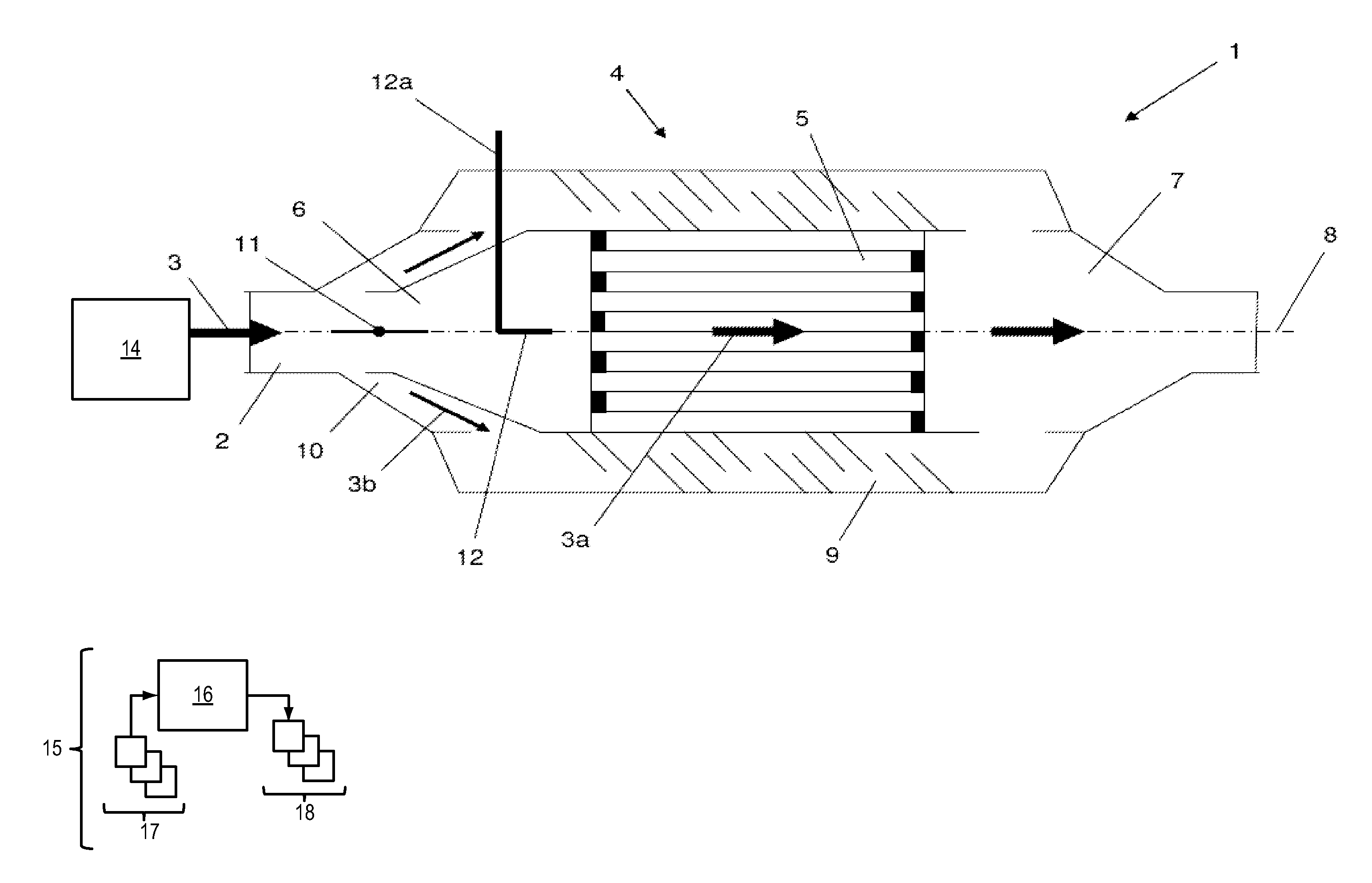
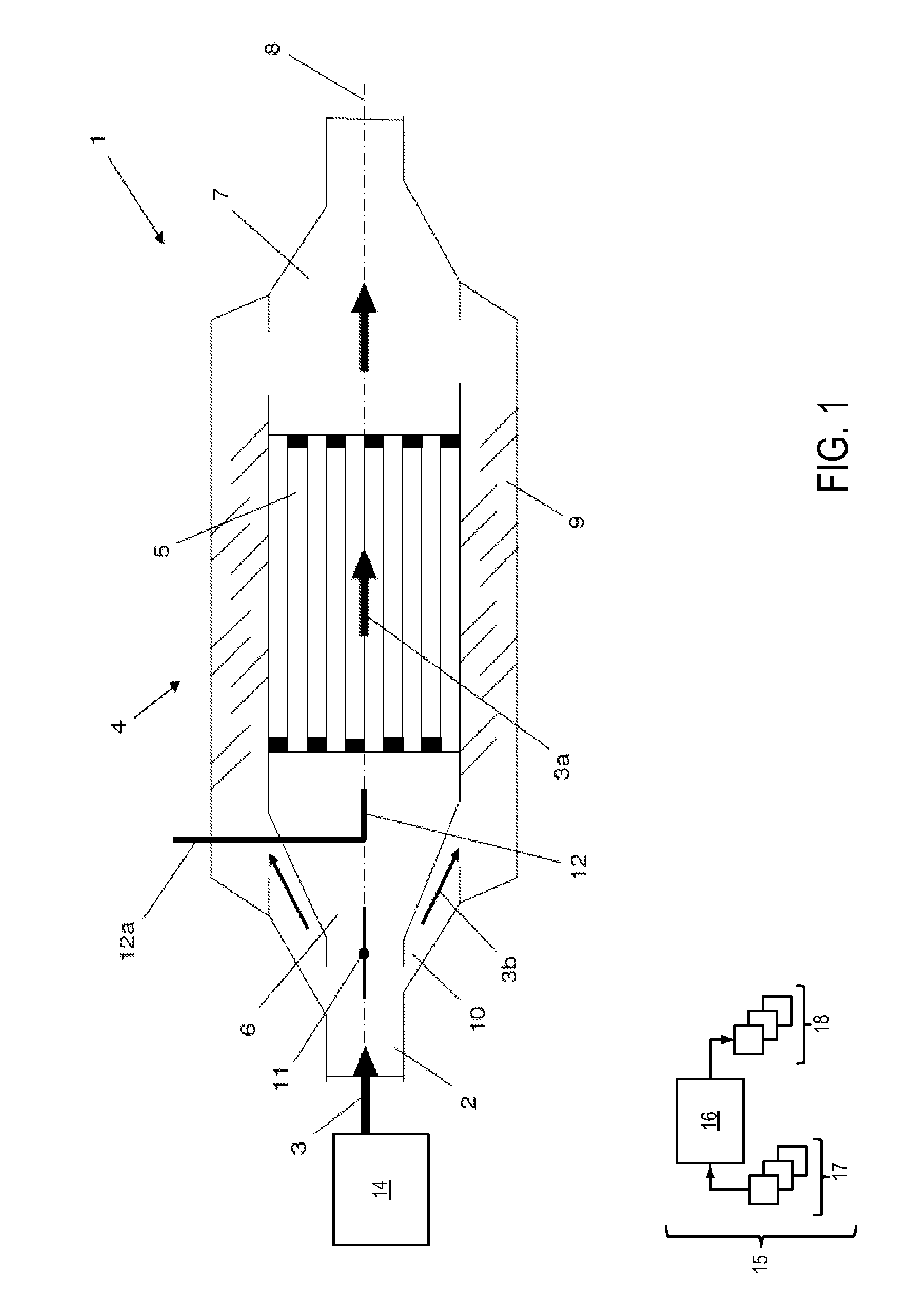
[0015]FIG. 1 shows an exhaust system or exhaust-gas aftertreatment system 1 coupled to an internal combustion engine 14, which may be an engine of a motor vehicle. In some examples, engine 14 is a diesel engine. Exhaust gas generated by the internal combustion engine flows in an exhaust-gas flow or path 3 through an exhaust line 2 in the direction of an outlet or exhaust tailpipe.

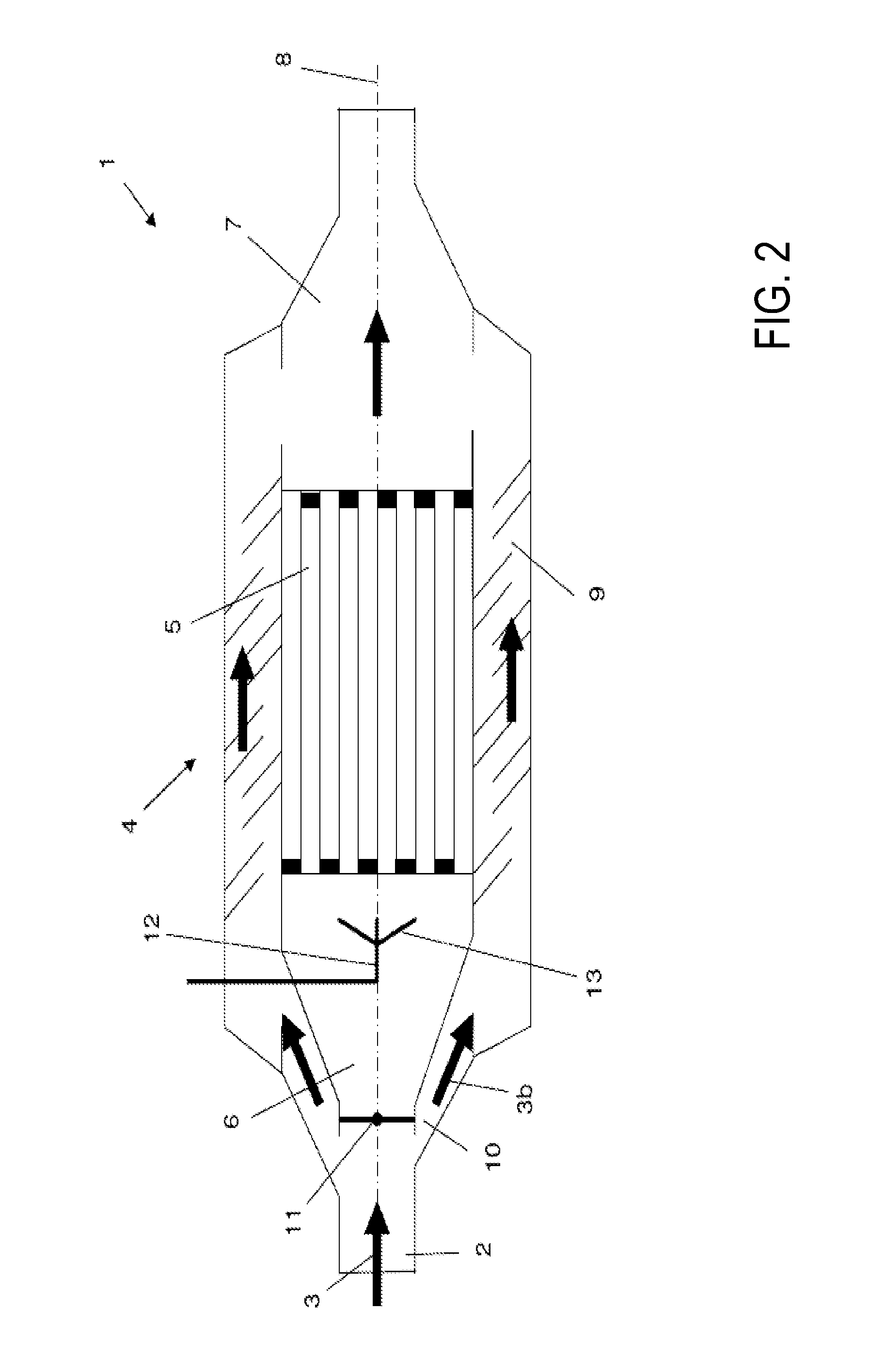
[0016]Arranged in the exhaust line 2 is a particulate filter 4, which may also be a constituent part of the exhaust line 2 or of the exhaust system 1. Particulate filter 4 filters particles out of the exhaust-gas flow 3 in order to reduce emissions. Exhaust-gas flow 3 runs in particulate filter 4 along one or more exhaust-gas paths 3a and 3b. Particulate filter 4 may have a cylindrical form, which harmonizes well with the tubular exhaust system.

[0017]Particulate filter 4 includes a primary fil...


PUM


Abstract

A particulate filter for a vehicle exhaust system includes a primary filter surrounded by a secondary filter and a quenching agent injection nozzle arranged upstream of the primary filter. In a normal mode, exhaust flows through the primary filter, and in a fail-safe mode or a mixed mode, at least some exhaust flows through the secondary filter and quenching agent is injected via the nozzle to cool the primary filter. The fail-safe or mixed modes may be enacted during an overload of the primary filter, for example. If engine shutdown is initiated during regeneration of the primary filter, a rate of quenching agent injection may be adjusted so that the regeneration may be completed at a safe temperature.

Description

RELATED APPLICATIONS[0001]The present application claims priority to German Patent Application No. 10 2011 076 154.3, filed on May 20, 2011, the entire contents of which are hereby incorporated by reference for all purposes.BACKGROUND AND SUMMARY[0002]Particulate filters may be included in engine exhaust systems to retain particles generated during fuel combustion. As engine exhaust flows through a particulate filter, particles such as soot accumulate in the filter, thereby reducing undesirable exhaust emissions. Because such filters become overloaded with exhaust particles over time, they must be regenerated periodically. Particulate filter regeneration may involve heating the filter to such an extent that the loaded particles may “burn off” or combust. In addition to reducing the particle loading so that additional particles may be retained, particulate filter regeneration helps to ensure a controlled level of exhaust-gas counter-pressure (i.e., pressure exerted on the flow of exh...

Claims


Application Information

Patent Timeline
IPC IPC(8): F01N3/023
CPCF01N3/04F01N2260/024F01N3/0238F01N3/2053Y02A50/20
Inventor YACOUB, YASSER MOHAMED SAYED
Owner FORD GLOBAL TECH LLC
Learn More