Noted in the prior art, such tools can be tiresome to use over a prolonged period of time.
In addition, there is always the possibility of misplacing or losing the tools, and they create the necessity for additional skill development or knowledge of
software systems; or they require the user to alternately
handle an object as needed, further restricting use of the user interface to the function of the specific object.
The deficiencies related to these software solutions result from the virtually unlimited physical differences in the
physical form of the user interface in terms of shape, size and skill, which make the generalization of specialized software solutions less effective.
The problem is the design assumes that the “pencil-like” device addresses the core deficiency of the relationship between the fingertip—in this instance, the hard surface of the touch device, and the software used to accept input.
The “pencil-like” device in fact is not the core deficiency, and therefore the solution proposed by Mortarelli further restricts the use of the finger to the
specific function of the “pencil-like” device.
The resulting solution does not solve the underlying problem of enhancing the user interface to be more in tune with how interaction with touch device technology naturally occurs.
However, Chamblin reverts back to some of the problems of the prior art, notably the need to carry a component that could be lost; the need to remove the component to perform other more general functions; and the creation of a social hurdle in terms of wearing a cumbersome device on the finger.
The core deficiency with this device, along with most of the prior art, is that the position of the
stylus, or “pencil-like” device, is made for the user.
These solutions simply remove the uniqueness of how each individual utilizes his or her body to interface with the touch device.
While the capacitive layer may work well in many situations, it does not respond to a pen, a
stylus or any other pointing instrument, for example.
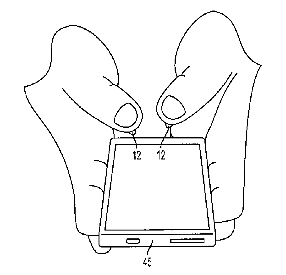
However, some individuals may find it difficult to simply register a
single point coinciding with a designated area of the touch-screen device.
This may be due to the size of the user digit contacting too much surface area of the touch-screen device, thereby registering too many points along the touch screen.
In addition, repetitive manipulation of a user's fingers to exacting positions during use of the touch screen may become tiresome and, in some case, run the risk of developing one or more
muscle complications from
repetitive movements.
However, as outlined above, using tools can be tiresome over a prolonged period of time and may risk the possibility of the tools being misplaced or lost.
Also, employing the use of an additional tool, such as a
stylus or a pen, can create the necessity for additional skill development or knowledge of software systems, or require the user to alternately
handle an object as needed, further restricting use of the user interface to the function of the specific object.
A need also exists for reducing or eliminating user fatigue during input and to overcome previous obstacles of the prior-art devices, including, for example, those related to shape, size and skill, which may make the generalization of applied specialized software solutions less effective.

