Image capture device and integrated circuit

a technology of image capture and integrated circuit, which is applied in the direction of color signal processing circuit, color television details, television systems, etc., can solve problems such as unstable images displayed, and achieve the effect of suppressing image blur

Inactive Publication Date: 2012-07-26
PANASONIC CORP
View PDF3 Cites 6 Cited by
  • Summary
  • Abstract
  • Description
  • Claims
  • Application Information

AI Technical Summary

Benefits of technology

[0024]According to the present invention, even when a plurality of persons are photographed over a long time, blurring of images can be suppressed, and the subject image at the start of capturing can be kept in the picture frame.

Problems solved by technology

In recent years, consumer digital still cameras and video cameras (hereinafter, will be referred to as “video movies”) have had unstable images displayed on screens thereof due to hand movement, and so on when capturing images.

Method used


Image

  • Image capture device and integrated circuit
  • Image capture device and integrated circuit
  • Image capture device and integrated circuit

Examples


first embodiment

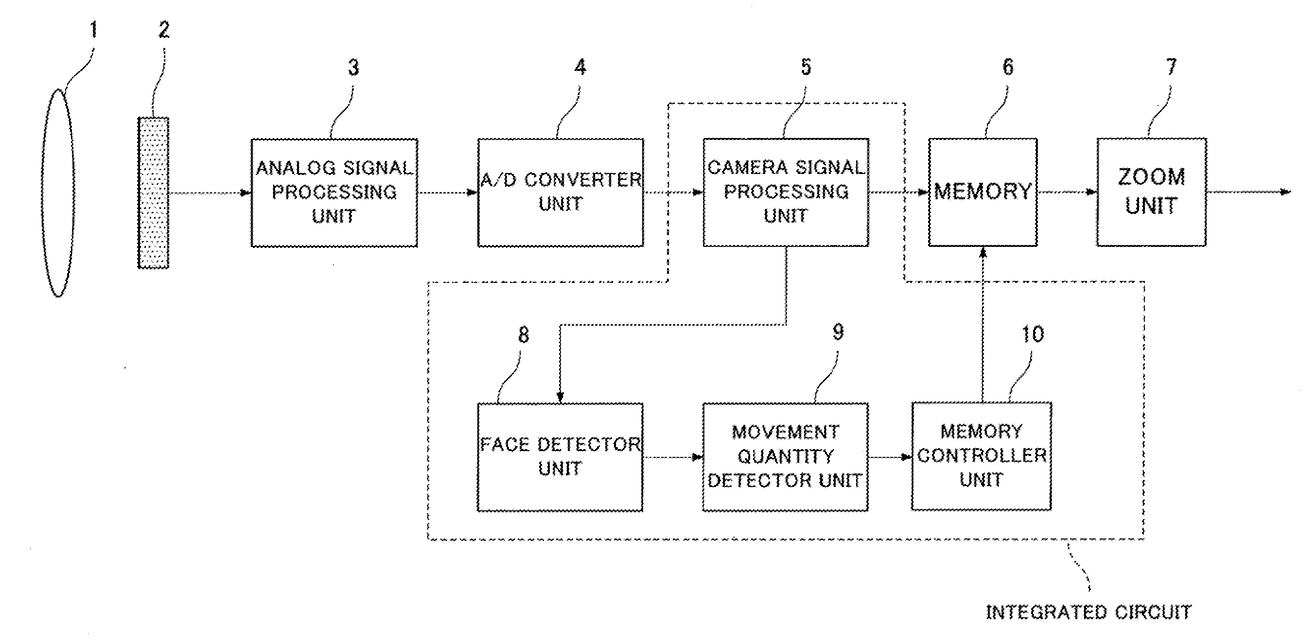
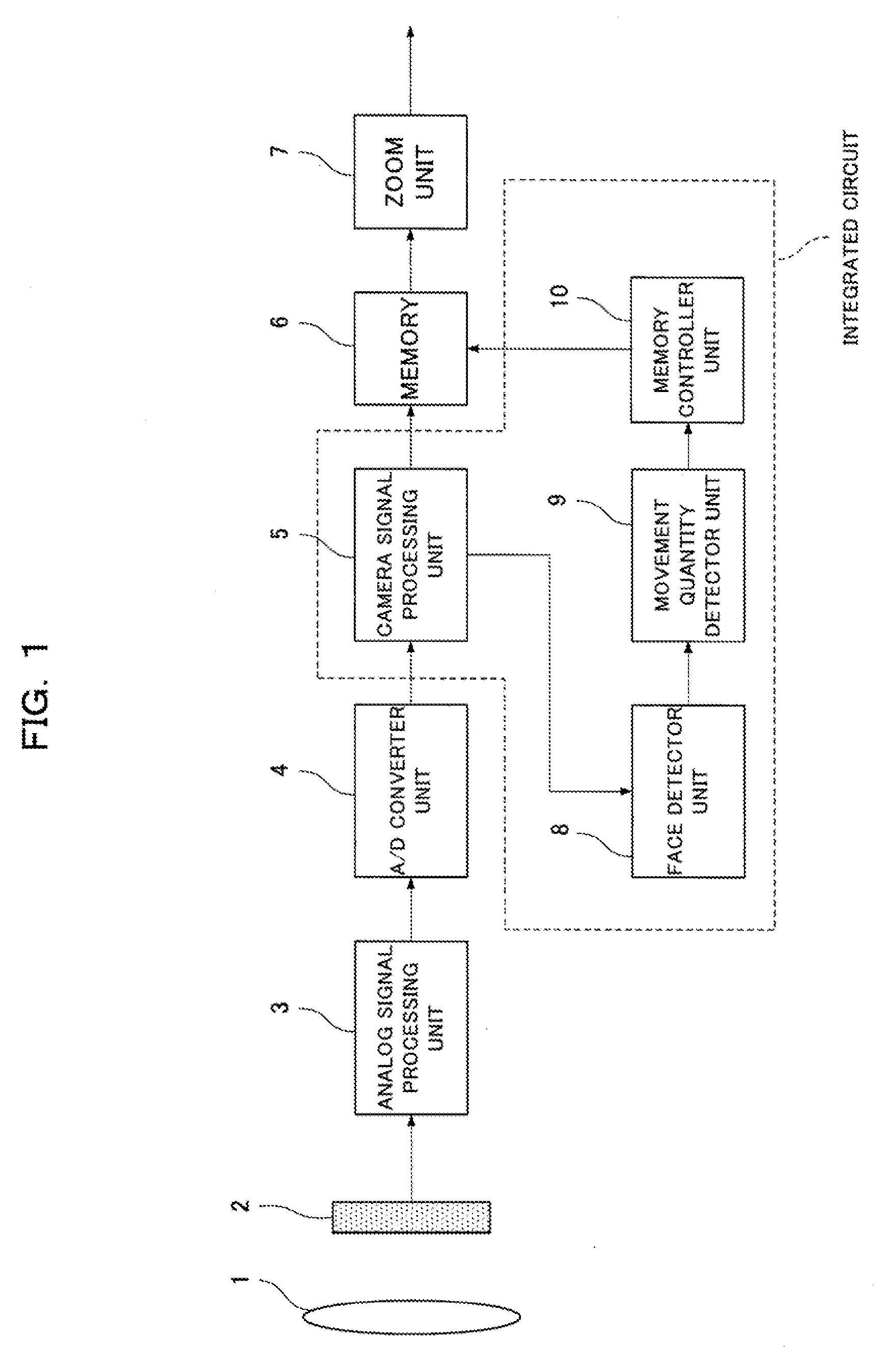
[0039]FIG. 1 is a block diagram of an image capture device according to a first embodiment of the present invention. The image capture device includes an image capture lens 1, an image capture element 2, an analog signal processing unit 3, an A / D converter unit 4, a camera signal processing unit 5, a memory 6, a zoom unit 7, a face detector unit 8, a movement quantity detector unit 9, and a memory controller unit 10.

[0040]The image capture lens 1 is an example of an imaging optical system which provides an optical image of a subject on the imaging surface of the image capture element 2. The image capture element 2 is a photoelectric conversion device which has the imaging surface and converts the optical image of the subject formed on the imaging surface into an electric signal (hereinafter, will be also referred to “an image signal”). The image capture element 2 is, for example, a CCD or MOS image sensor. A period in which the image capture element 2 of the present embodiment can c...

second embodiment

[0055]An image capture device according to a second embodiment of the present invention will be described with reference to FIG. 7. In the present embodiment, the configuration of a correction optical mechanism for decentering or tilting the optical axis of the imaging optics will be described as a motion correction unit for correcting the motion of a subject image. The same elements in FIG. 7 as in FIG. 1 of the first embodiment are indicated by the same reference numerals, and an explanation thereof is omitted.

[0056]FIG. 7 is a block diagram of the image capture device according to the second, embodiment of the present invention. An imaging optical system 20 is composed of four lens groups L1, L2, L3, and L4. The lens group L2 moves in the optical axis direction to perform zooming, and the lens group L4 moves in the optical axis direction to perform focusing. The lens group L3 is composed of two lens groups L31 and L32 which are disposed closer to the imaging area than the lens gr...

third embodiment

[0059]An image capture device according to a third embodiment of the present invention will be described with reference to FIG. 8. In the present embodiment, the combined use of a correction optical mechanism for decentering or tilting the optical axis of the imaging optics and image read control from a memory 6 will be described as a unit for correcting the motion of subject image. The same elements in FIG. 8 as in FIG. 1 of the first embodiment and FIG. 7 are indicated by the same reference numerals, and an explanation thereof is omitted.

[0060]FIG. 8 is a block diagram of the image capture device according to the third embodiment of the present invention. In the present embodiment, the units for correcting the motion of an image (the image read control from the memory 6 and the correction optical mechanism) in the above-described two embodiments are combined, so that the motion correction effect of the subject image can be further increased.

[0061]Specifically, the correction optic...


PUM


Abstract

Provided is an image capture device capable of suppressing blurring of images and keeping a subject image at the start of capturing in the picture frame, even when a plurality of objects such as persons are photographed over a long time. The image capture device includes: an imaging optical system 1; an image capture element 2; a feature detector unit (face detector unit 8) for detecting the features of the objects contained in an image represented by an image signal obtained by the image capture element 2; a movement quantity detector unit for detecting the movement quantities of the features including the face regions of the human figures; and a composition change correction unit for correcting a change in the composition of the image based on the movement quantities of the face regions.

Description

TECHNICAL FIELD[0001]The present invention relates to image blur Correction devices for correcting changes of compositions such as movements of images due to movements of image capture devices, and so on.BACKGROUND ART[0002]In recent years, consumer digital still cameras and video cameras (hereinafter, will be referred to as “video movies”) have had unstable images displayed on screens thereof due to hand movement, and so on when capturing images. In order to solve the problem, digital still cameras and video movies including image blur correction devices have been developed or commercialized.[0003]For example, there has been a method in which a variable angle prism is provided for the optical system of an image capture device, the movement of the image capture device is detected by an acceleration sensor, and according to the detection result, the variable angle prism is drivingly controlled to correct the motion of an image (e.g., see Patent Literature 1).[0004]As another example,...

Claims


Application Information

Patent Timeline
Patent Type & Authority Applications(United States)
IPC IPC(8): H04N5/14H04N5/228
CPCH04N5/232H04N5/23248H04N5/23222H04N5/23219H04N23/61H04N23/64H04N23/611H04N23/68H04N23/635
Inventor KUSAKA, HIROYA
Owner PANASONIC CORP
Why Eureka
Try Eureka