
Injection Device with Sealed Luer Fitting

Active Publication Date: 2012-07-26
BECTON DICKINSON & CO
View PDF3 Cites 16 Cited by
  • Summary
  • Abstract
  • Description
  • Claims
  • Application Information

AI Technical Summary

Benefits of technology

[0019]The present invention relates generally to an injection device for delivering a dose of medicament by injection and having a shield system for preventing contamination of the injection device during its operation. For example, the injection device can be a prefilled compression syringe. The injection device has a syringe body defining a compressible reservoir for containing a dose of medicament. A male luer fitting is provided and has a channel therethrough for conducting contents of the reservoir and is defined by an outer surface, a base end connected to the syringe body, and a luer tip at an end of the male luer fitting opposing the base end. A shield cap is arranged on and sealed against the male luer fitting at a first position prior to use of the injection device. The shield cap can be rotated about or moved along an axis of the male luer fitting during movement from the first position to a second position.
[0020]A first seal is provided for sealing the channel at the luer tip of the male luer fitting and preventing leakage therethrough of content from the reservoir at least when the shield cap is at the first position. In one example, the luer tip can be sealed by the first seal in the form of a membrane closing the channel of the male luer fitting. In such a case, the shield cap can be formed with a sharp tip facing the luer tip when the shield cap is in the first position. For example, the sharp tip can comprise a needle bonded to the shield cap. The sharp tip is capable of puncturing or cutting the first seal when the shield cap is moved from the first position to the second position.
[0025]A second seal is arranged between the shield cap and the male luer fitting for protecting the outer surface and the luer tip of the male luer fitting from outside contamination when the shield cap is arranged at the first position. The second seal is formed by a first connecting structure formed on the male luer fitting between the base end and the luer tip and a second connecting structure formed on the shield cap. The first and second connecting structures interact with each other to prevent inadvertent movement of the shield cap relative to the male luer fitting when the shield cap is arranged at the first position.
[0031]The present invention also relates to a method of dispensing contents of a compressible reservoir of an injection device through a male luer fitting connected to the injection device. The method includes placing a shield cap at a first position on the male luer fitting; sealing, with a first seal, a luer tip preventing leakage therethrough of content from the reservoir of the syringe at least when the shield cap is at the first position; and sealing an outer surface of the luer tip from outside contamination by a second seal formed by first and second connecting structures on the male luer fitting and the shield cap, respectively, when the shield cap is arranged at the first position. For example, the first seal includes a sealing piece seated in an opening on the luer tip when the shield cap is in the first position. The second seal is formed by ribs or circumferential rings arranged on the shield cap and the male luer fitting. In one example, the step of sealing a luer tip can comprise sealing the luer tip with a twist-off tab connected to the male luer fitting by a frangible connection.

Problems solved by technology

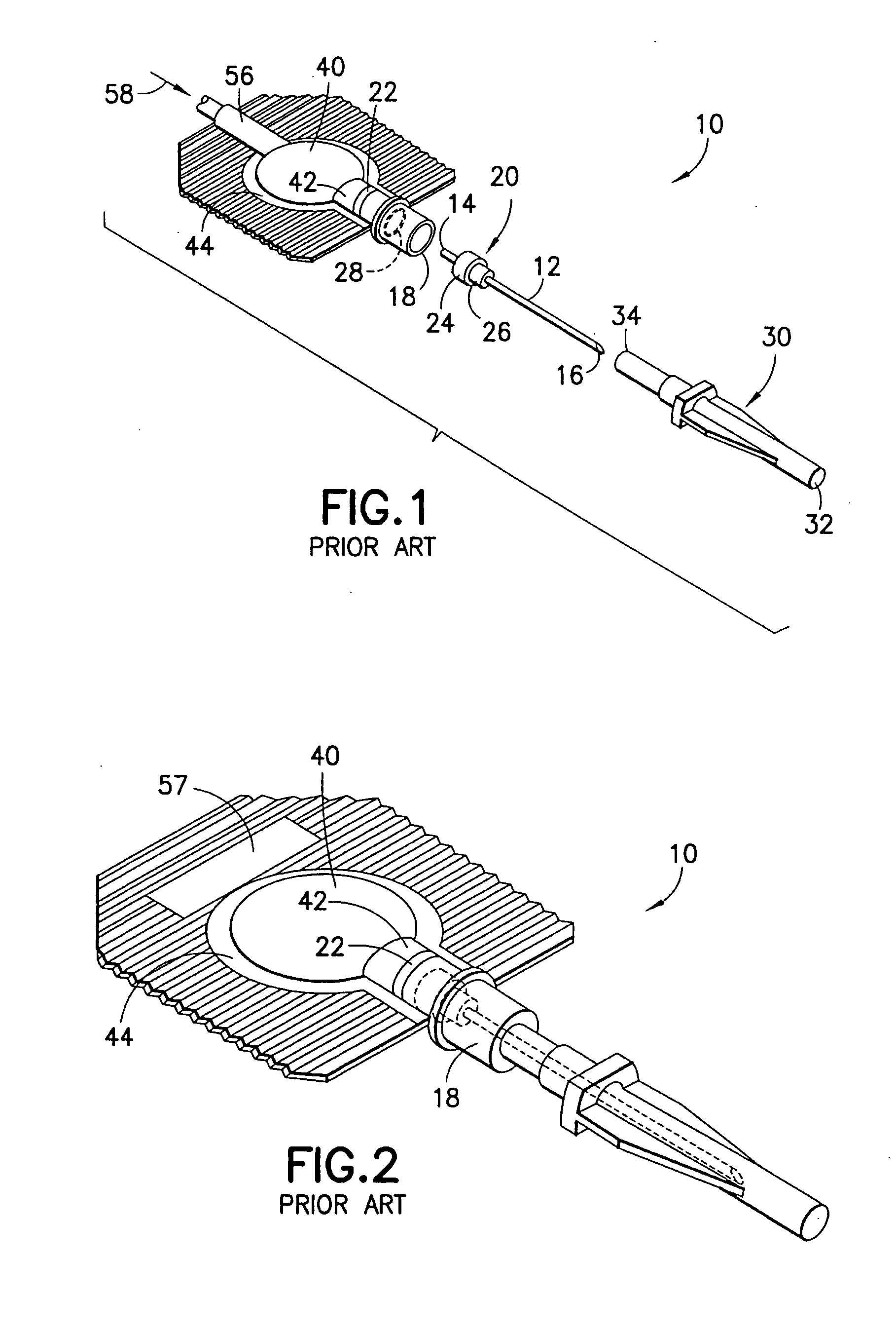
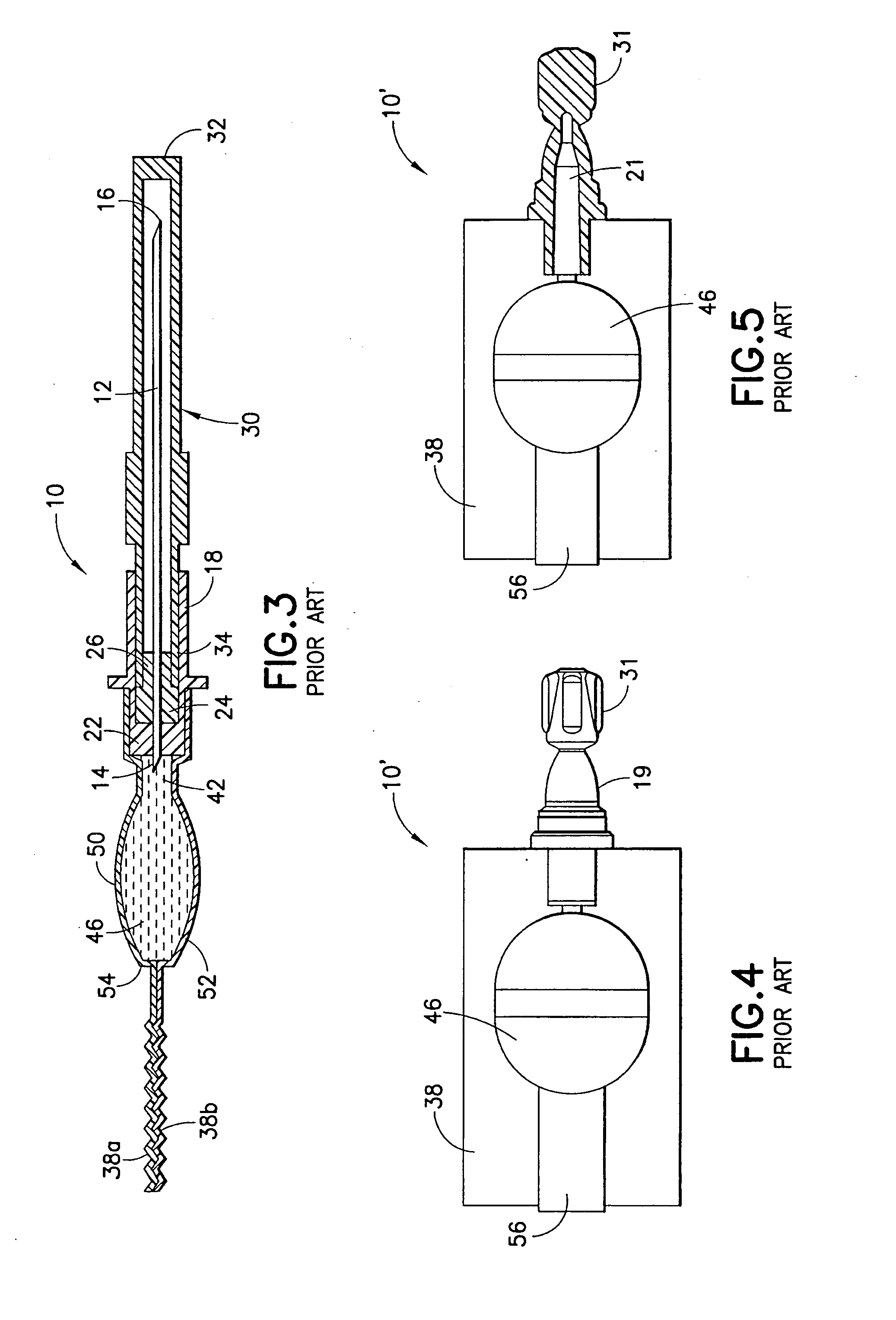
The above described compression syringe 10 is however incompatible with a luer connector and unable to administer the medicament through a luer connector.
Such cap 31 however can be accidentally damaged or removed during shipping or handling of the luer-type syringes 10′ causing such syringes 10′ unfit for their normal use.
These and other disadvantages can adversely affect the operation of such luer-type syringes 10.

Method used


Image

  • Injection Device with Sealed Luer Fitting
  • Injection Device with Sealed Luer Fitting
  • Injection Device with Sealed Luer Fitting

Examples


Embodiment Construction

[0071]The various injection devices described herein are formed to store a dose of medicament and deliver the same by injection. Although compression syringes are shown in the various drawing figures as examples of the injection devices, the invention is not limited to such compression syringes.

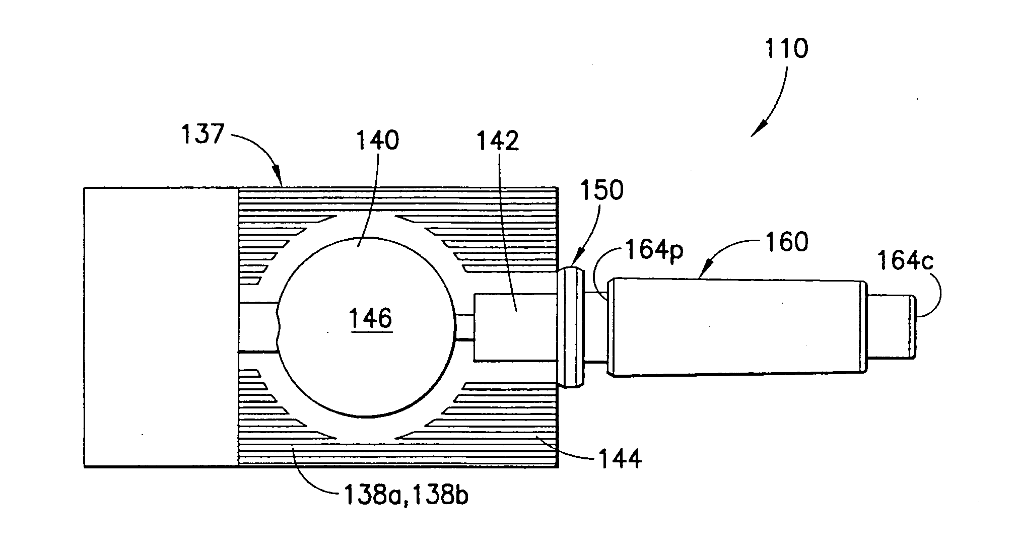
[0072]FIGS. 6 to 11 illustrate an injection device 110 according to a first embodiment of the invention. The injection device 110 is shown as a compression syringe including a syringe body 137 defining a reservoir 146 for storing medicament. The syringe body 137 is at least partially compressible for expelling the medicament into a male luer fitting 150, which will be described in detail below. The reservoir 146 is formed from a pair of flexible sheets 138a and 138b of thermoplastic material. Each of the sheets 138a, 138b can have a central portion 140, an expanded injection neck portion 142, and a substantially flat peripheral portion 144. At least a portion of the sheets 138a, 138b forming ...


PUM


Abstract

The invention relates to an injection device (110) with a luer fitting. The injection device has a compressible syringe body (137) defining a reservoir (146). A male luer fitting (150) has a channel (152) therethrough for conducting contents of the reservoir, and a luer tip at an end of said male luer fitting opposing said base end. A first connecting structure (182) is arranged on said male luer fitting between said base end and said luer tip. A shield cap (160) is arranged on the male luer fitting. The shield cap has a second connecting structure interacting with said first connecting structure to prevent inadvertent movement of said shield cap relative to said male luer fitting when said shield cap is arranged at said first position. A first seal (170) is provided for sealing said channel at said luer tip. A second seal (180) is arranged between said shield cap and said male luer fitting for sealing the outer surface and the luer tip of said male luer fitting from outside contamination.

Description

BACKGROUND OF THE INVENTION[0001]1. Field of the Invention[0002]The present invention relates generally to a prefilled injection device for delivering a dose of medicament by injection and having a sealing system for preventing contamination of the injection device prior to its usage. More particularly, the present invention is directed to a syringe assembly including a sealed luer fitting.[0003]2. Description of the Related Art[0004]Syringes used for the delivery of medicaments to patients are well known. Oftentimes syringes are prefilled with a dosage of a medicament or other substance by a pharmaceutical manufacturer and then distributed to end users such as health care professionals or patients for administration of the prefilled dosage of medicament.[0005]A “compression syringe” used herein refers to a syringe which holds medicament in a reservoir defined by walls with at least one being compressible when squeezed by a user's hand. Compression syringes can be prefilled with a s...

Claims


Application Information

Patent Timeline
IPC IPC(8): A61M5/32
CPCA61M5/282A61M2005/312A61M2005/3104A61M5/3213A61M5/3293A61M2005/314
Inventor CHIA, YU LENG NEVILLEHAUSSER, RODERICKNGUYEN HUU, XUA HUYENLEE, HOONG SIMLIM, HONG TAT TEDDY
Owner BECTON DICKINSON & CO
Learn More