
Front/rear wheel brake control device

a control device and rear wheel technology, applied in the direction of mechanical control devices, bicycle brakes, instruments, etc., can solve the problems of bike body sliding and causing an unsecured steering, uncomfortable riding or even endangering the rider, and the risk of being easily toppled over, so as to improve the aforementioned drawbacks, improve the safety of braking, and improve the effect of comfor

Inactive Publication Date: 2012-08-02
LO JEN FA
View PDF14 Cites 8 Cited by
  • Summary
  • Abstract
  • Description
  • Claims
  • Application Information

AI Technical Summary

Benefits of technology

[0008]Therefore, it is a primary objective of the present invention to provide an improved front / rear wheel brake control device to improve the aforementioned drawbacks and provide the effects of safe braking and comfortable riding.
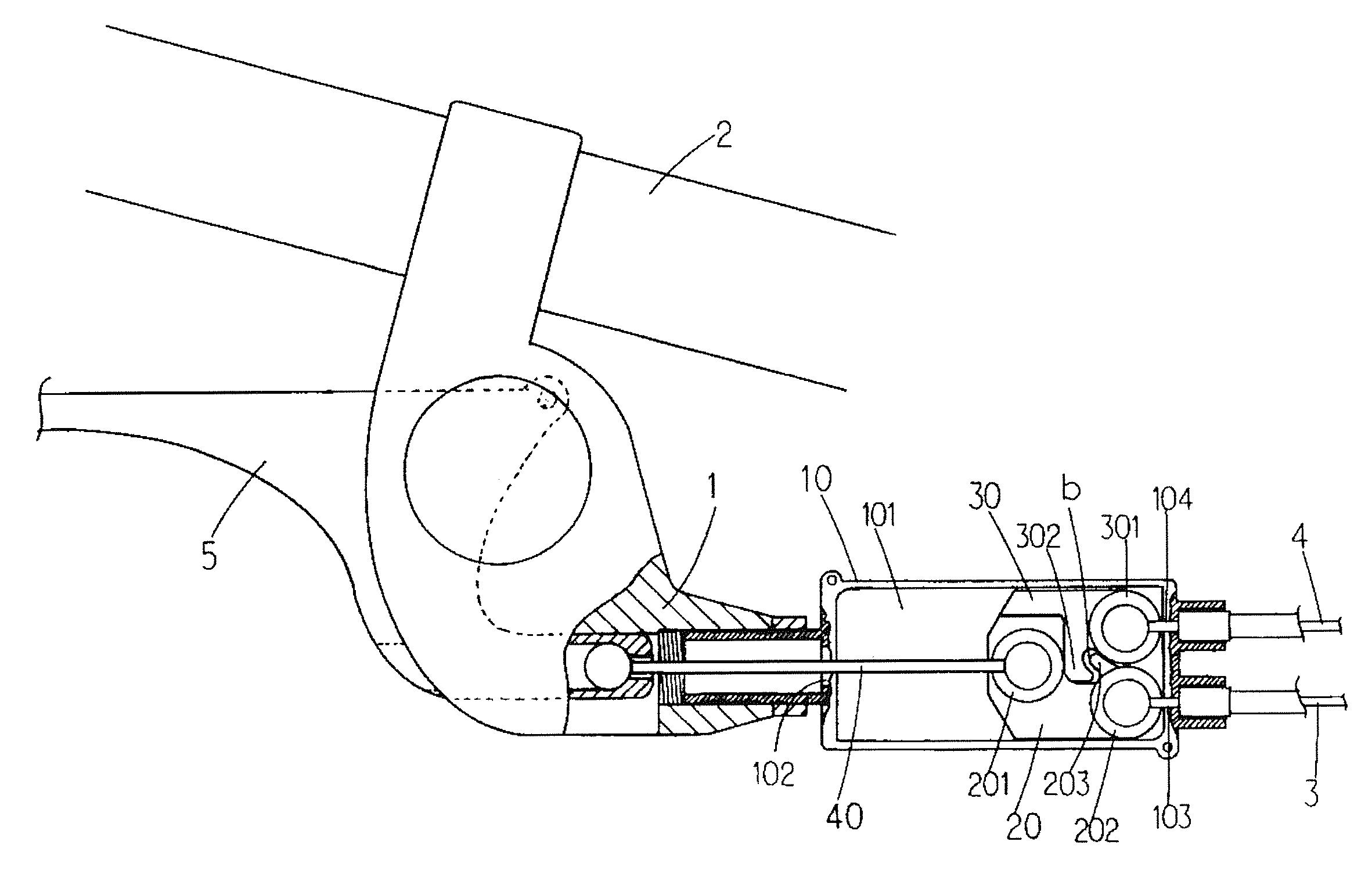
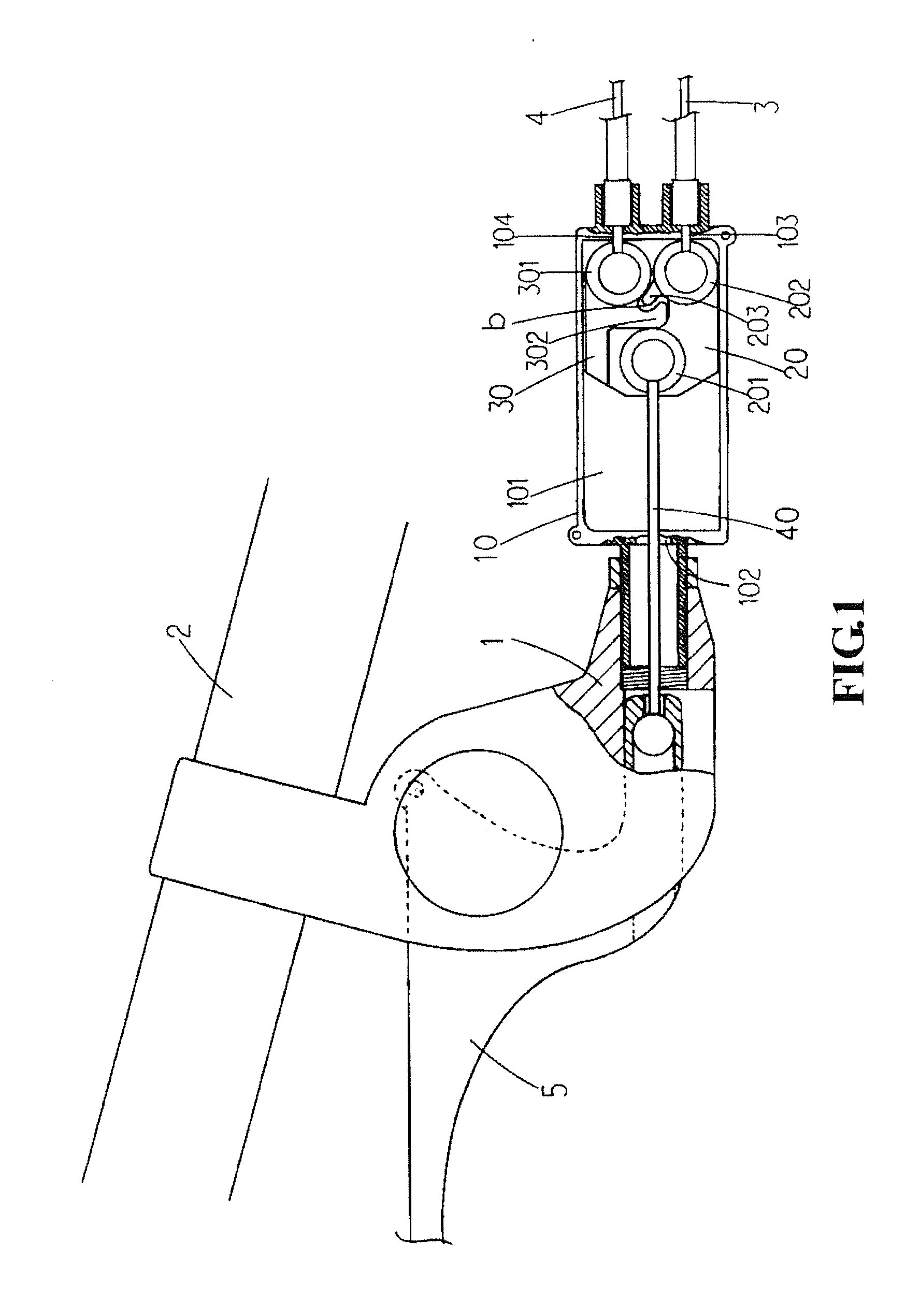
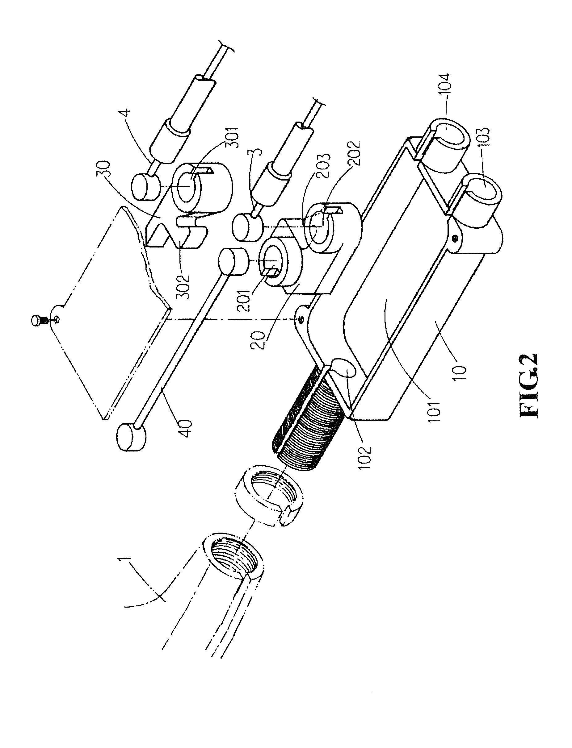
[0009]To achieve the aforementioned objective, the present invention accommodates a first driving member and a second driving member in a control member, and the first and second driving members are coupled to brake lines of the rear wheel and front wheel respectively, and the first and second driving members are coupled with each other and moved back and forth in the control member, wherein the first driving member is coupled to the brake handle through the control line, and the second driving member is delayed and driven by the first driving member; such that when the brake handle is operated, the first driving member will be linked and moved to brake the rear wheel corresponding to the brake line, and the delayed and driven second driving member will brake the front wheel corresponding to the brake line, so as to achieve the safe, comfortable, and sectional braking operation effect by braking the rear wheel first and then immediately braking the front wheel by operating the brake handle while the bike body is moving.

Problems solved by technology

1. When the rider's right hand presses the right brake handle for the braking operation of the front wheel only, the rear wheel keeps rolling forward to push a bike body, so that the bike body has the risk of being toppled over easily.
2. When the rider's left hand presses the left brake handle for the braking operation of the rear wheel only, the front wheel keeps rolling forward to roll and drag the bike body, so that the bike body has the risk of sliding and causing an unsecured steering.
3. When the rider's left and right hands press the left and right brake handles simultaneously for the braking operation of the rear and front wheels, the front and rear wheels are stopped immediately, and the inertia of the bike may move the rider forward to cause an uncomfortable ride or even endanger the rider.

Method used


Image

  • Front/rear wheel brake control device
  • Front/rear wheel brake control device
  • Front/rear wheel brake control device

Examples


Embodiment Construction

[0015]With reference to FIGS. 1 and 2 for an improved front / rear wheel brake control device of the present invention, the front / rear wheel brake control device comprises: a control member 10, installed at the brake handle body 1 or the bike handle 2 or another position of the bike body, and having an accommodating portion 101, a through hole 102 formed at an end of the accommodating portion 101 and interconnected to the outside, left and right through holes 103, 104 formed at the other end of the accommodating portion 101 and interconnected to the outside; a first driving member 20, installed on a side inside the accommodating portion 101 of the control member 10 and capable of being moved back and forth, and having a hinge portion 201, 202 formed separately at both ends of the first driving member 20, and a connecting latch 203 disposed on a side of the first driving member 20, and the two hinge portions 201, 202 are coupled to the through hole 102 at an end of the control member 1...


PUM


Abstract

A front / rear brake control device applicable for bicycles, electric bicycles or motorcycles includes a first driving member and a second driving member accommodated in a control member, coupled to each other and brake lines of the rear and front wheels respectively, and moved in the control member reciprocally. The first driving member is coupled to the brake handle through the control line, and the second driving member is delayed and driven by the first driving member. When the brake handle is operated, the first driving member links and moves the corresponding brake line to brake the rear wheel, and then the delayed and driven second driving member brakes the front wheel by the corresponding brake line, such that the brake handle of the bike body can be operated to brake the rear wheel first, and then the front wheel to achieve a safe, comfortable and sectional braking operation.

Description

BACKGROUND OF THE INVENTION[0001]1. Field of the Invention[0002]The present invention relates to an improved front / rear brake control device, in particular to the brake control device featuring a simple assembly and an easy and convenient operation and providing a safer and more comfortable transportation means such as a bicycle, an electric bicycle or a motorcycle.[0003]2. Description of the Prior Art[0004]As front and rear wheels of a general bicycle or motorcycle are installed with a brake separately, and the brakes are connected to the left and right brake handles through a brake line, wherein the left brake handle is provided for controlling the braking of the rear wheel, and the right brake handle is provided for controlling the braking of the front wheel. In general, the left and right brake handles are installed on left and right handles of the bicycle or motorcycle respectively, so that a rider's left and right hands can control the braking of the rear wheel and the front w...

Claims


Application Information

Patent Timeline
IPC IPC(8): B62L3/08F16C1/16B62L3/02F16C1/12
CPCB60T11/046B60T11/06Y10T74/20012B62L3/08B62L3/02
Inventor LO, JEN-FA
Owner LO JEN FA
Learn More