Electroluminescent device multilevel-drive chromaticity-shift compensation

a technology of chromaticity shift compensation and electroluminescent devices, which is applied in the field of compensating for chromaticity shift of emitters, can solve the problems of color saturation loss, scaling cannot be restored, color errors, etc., and achieve the effect of providing chromaticity shift compensation and reducing bit depth

Active Publication Date: 2012-08-02
GLOBAL OLED TECH
View PDF3 Cites 12 Cited by
  • Summary
  • Abstract
  • Description
  • Claims
  • Application Information

AI Technical Summary

Benefits of technology

[0045]g) providing the black, first and second percentages to the drive circuit to cause it to provide the black, first and second current densities to the EL emitter for the black, first and second percentages, respectively, of the selected emission time, so that the integrated light output of the EL emitter during the selected emission time has an output luminance and output chromaticity colorimetrically indistinct from the designated luminance and selected chromaticity, respectively, whereby the chromaticity shift of the EL emitter is compensated.
[0046]An advantage of this invention is an EL device that compensates for chromaticity shift of the organic materials in the device without requiring extensive lookup tables. A further advantage of this invention is that it can provide chromaticity-shift compensation for EL devices that have only a single color of EL emitter, such as EL lamps. It is an important feature of this invention that it makes productive use of changes in chromaticity with current density which have hitherto been considered undesirable. It permits the adjustment of luminance independently of chromaticity. In some embodiments, it can use lower bit depth than conventional digital drive schemes. It advantageously permits the reproduction of colors that lie off the chromaticity locus of a particular EL emitter.

Problems solved by technology

These methods are complicated by image structure limitations because they typically involve non-continuous tone systems, but because the white of a subtractive CMYK image is determined by the substrate on which it is printed, these methods remain relatively simple with respect to color processing.
Attempting to apply analogous algorithms in continuous tone additive color systems would cause color errors if the additional primary is different in color from the display system white point.
However, the scaling cannot restore, for all colors, all of the color saturation lost in the addition of white.
The lack of a subtraction step in this method ensures color errors in at least some colors.
Additionally, Morgan's disclosure describes a problem that arises if the white primary is different in color from the desired white point of a display device, but does not adequately solve the problem.
The method simply accepts an average effective white point, which effectively limits the choice of white primary color to a narrow range around the white point of the device.
The method of Lee et al. suffers from a similar color inaccuracy to that of Morgan.
Because of its similarity to the CMYK algorithm, it suffers from the same problem cited above, namely that a white pixel having a color different from that of the display white point will cause color errors.
This problem can affect white subpixels in OLED or EL displays.
While a number of other methods have addressed the problem of transforming three color-input signals to four color-output signals, e.g., Morgan et al. in U.S. Pat. No. 6,453,067, Choi et al. in US 2004 / 0222999, Inoue et al. in US 2005 / 0285828, van Mourik et al. in WO 2006 / 077554, Chang et al. in US 2006 / 0187155, and Baek in US 2006 / 0256054, these methods cannot adjust for a white emitter with variable c
gnals. This method is computationally and memory intensive, and would be slow and difficult to implement in a large d
isplay. Gathering data for the method requires manual adjustments that can be time-consuming and labor-in
tensive. It requires gathering spectral data, which is more complex and time-consuming than colorimetric meas
urements. Further, it does not mathematically provide a colorimetric match between a desired RGB color and the RGBW e
However, the AM modulation does not provide control of chromaticity or luminance.
However, this scheme is limited to only chromaticities the EL emitter can produce natively.
This is not sufficient for full-color displays, in which the desired chromaticity may not lie on the chromaticity locus of the EL emitter.

Method used


Image

  • Electroluminescent device multilevel-drive chromaticity-shift compensation
  • Electroluminescent device multilevel-drive chromaticity-shift compensation
  • Electroluminescent device multilevel-drive chromaticity-shift compensation

Examples


Embodiment Construction

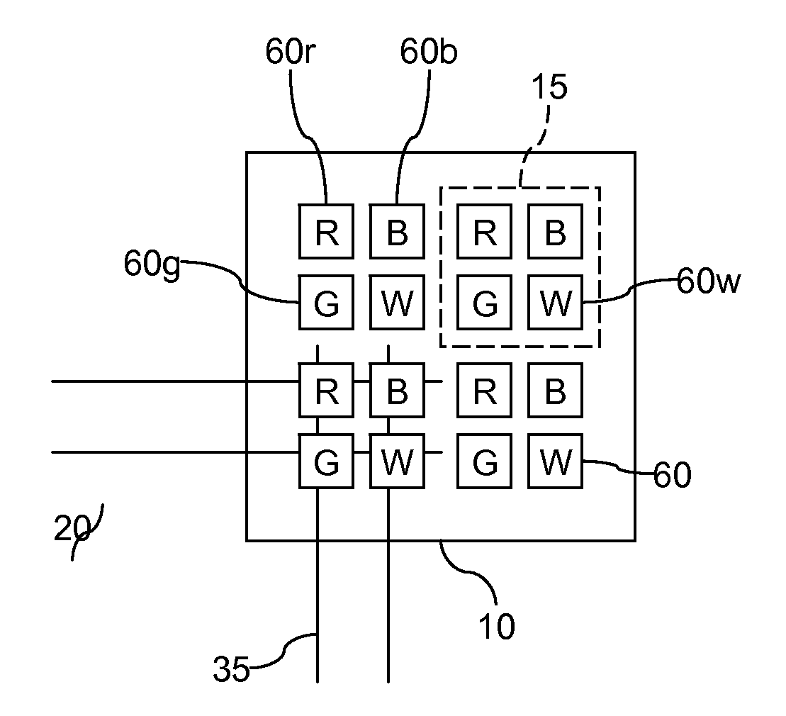
[0059]FIG. 9 shows a plan view of an EL display 10 according to an embodiment. EL display 10 has an array of a plurality of EL subpixels 60 arranged in rows and columns and emitting various colors. Subpixels 60r emit substantially red light, subpixels 60g emit green, subpixels 60b emit blue, and subpixels 60w emit broadband light, such as yellow or white. “Broadband light” means light with a broader spectral bandwidth than red, green or blue, e.g., light with a full width at half maximum (FWHM) larger than the FWHM of red, green or blue. Adjacent RGBW subpixels 60r, 60g, 60b, 60w together compose a pixel 15.

[0060]EL display 10 includes a plurality of row select lines 20; each row of EL subpixels 60 has a corresponding select line 20. EL display 10 further includes a plurality of data lines 35 where each column of EL subpixels 60 has an associated data line 35 for readout. Each subpixel 60 includes an EL emitter 50 (FIG. 7). Each subpixel is connected to a respective one of the data ...


PUM


Abstract

Compensation for chromaticity shift of an electroluminescent (EL) emitter having a luminance and a chromaticity that both correspond to current density is performed. Different black, first and second current densities are selected based on a received designated luminance and a selected chromaticity, each current density corresponding to emitted light colorimetrically distinct from the light emitted at the other two current densities. Respective percentages of a selected emission time are calculated for each current density to produce the designated luminance and selected chromaticity. The current densities are provided to the EL emitter for the calculated respective percentages of the emission time so that the integrated light output of the EL emitter during the selected emission time is colorimetrically indistinct from the designated luminance and selected chromaticity.

Description

CROSS REFERENCE TO RELATED APPLICATION[0001]Reference is made to commonly-assigned, co-pending U.S. patent application Ser. No. 12 / 191,478, filed Aug. 14, 2008, entitled “OLED device with embedded chip driving” by Winters et al. and published as US 2010-0039030, to commonly-assigned, co-pending U.S. patent application Ser. No. 12 / 272,222, filed Nov. 17, 2008, entitled “Compensated drive signal for electroluminescent display” by Hamer et al. and published as US 2010-0123649, and to commonly-assigned, co-filed U.S. Patent Application filed under Attorney's Docket 001444-5350, entitled “Electroluminescent device aging compensation with multilevel drive” by White, the disclosures of which are incorporated by reference herein.FIELD OF THE INVENTION[0002]The present invention relates to solid-state electroluminescent (EL) devices such as organic light-emitting diode (OLED) displays, and particularly to compensation for chromaticity shift of emitters in such devices.BACKGROUND OF THE INVEN...

Claims


Application Information

Patent Timeline
Patent Type & Authority Applications(United States)
IPC IPC(8): G09G5/10G09G3/30
CPCG09G3/2003G09G3/2018G09G3/2081G09G3/3233G09G2300/0452G09G2320/0666G09G2320/0247G09G2320/0261G09G2320/0285G09G2320/043G09G2310/0297
Inventor WHITE, CHRISTOPHER J.HAMER, JOHN W.
Owner GLOBAL OLED TECH
Why Eureka
Try Eureka