Conduction breaking device

a technology of conduction breaking and splicing switch, which is applied in the direction of electrical equipment, emergency protective circuit arrangements, and severing switches of conductors, etc., can solve the problems of increasing manufacturing costs, enlarge the installation space, and activate the conduction breaking device, and achieve the effect of reliable breaking of conduction and increasing the siz

Inactive Publication Date: 2012-08-02
TOYODA GOSEI CO LTD
View PDF3 Cites 15 Cited by
  • Summary
  • Abstract
  • Description
  • Claims
  • Application Information

AI Technical Summary

Benefits of technology

[0007]Accordingly, it is an objective of the present invention to provide a conduction...

Problems solved by technology

When an abnormality occurs in the electrical devices, the conduction breaking device is activated to break the conduction...

Method used


Image

  • Conduction breaking device
  • Conduction breaking device
  • Conduction breaking device

Examples


Embodiment Construction

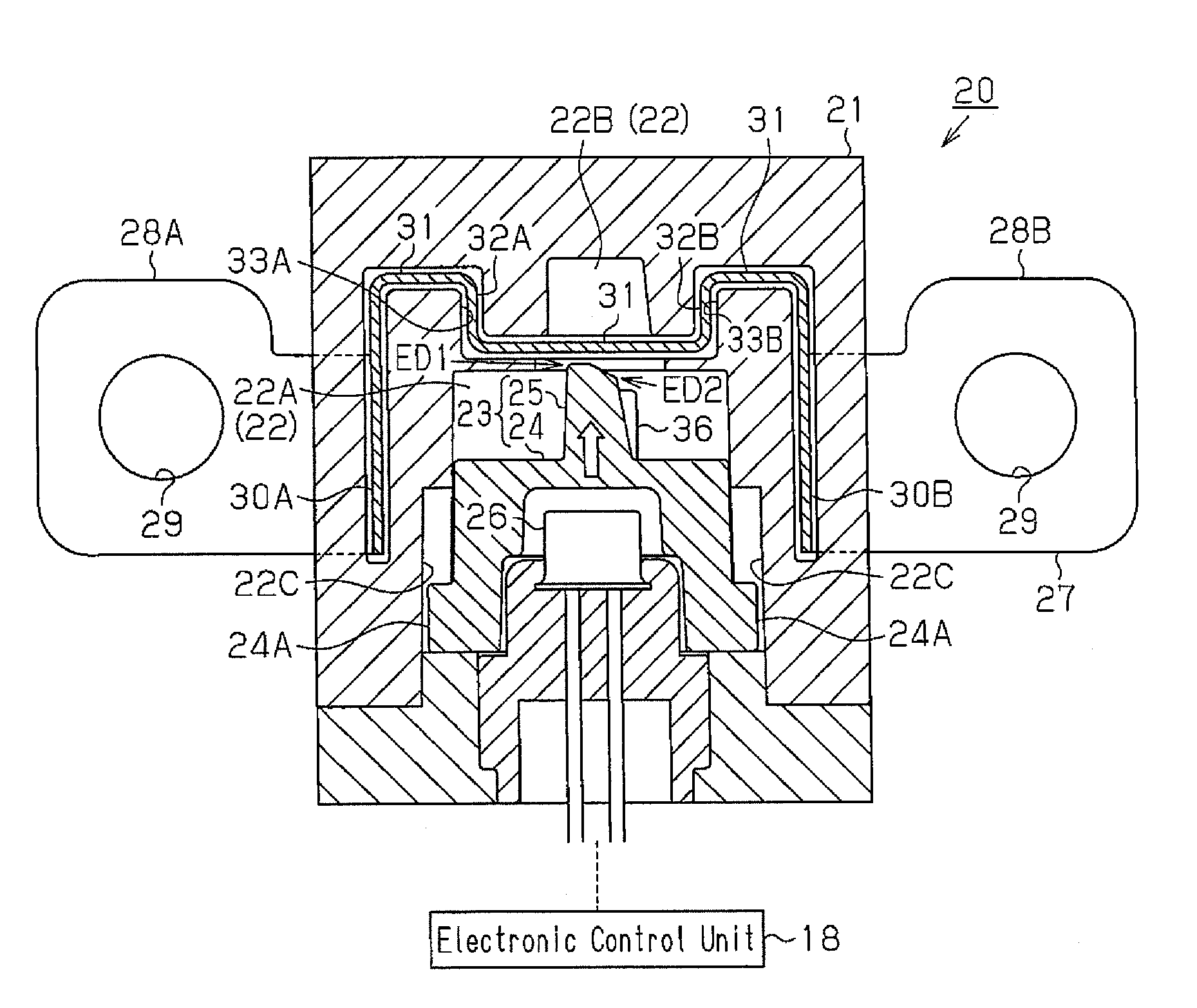
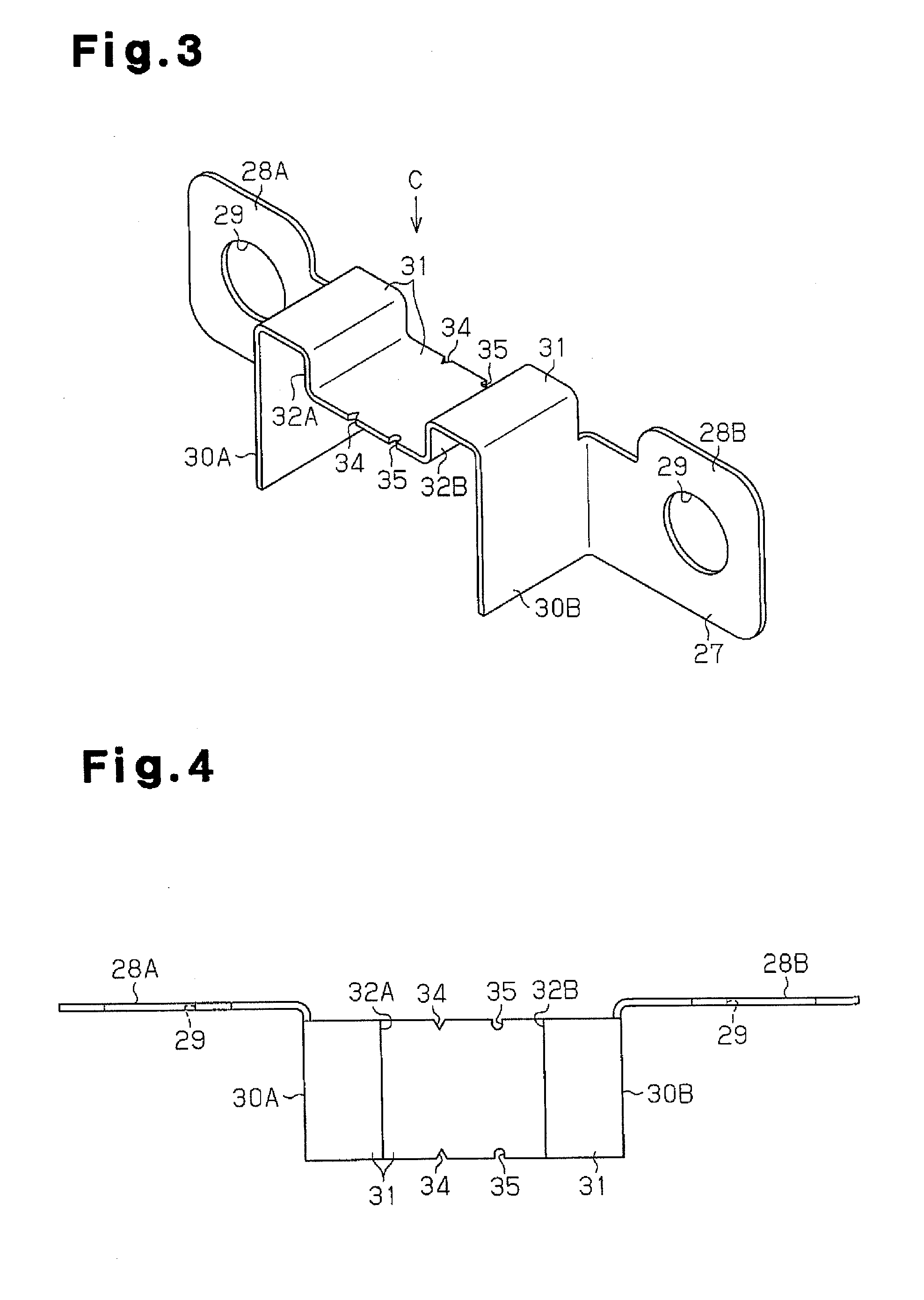
[0025]A conduction breaking device 20 according to one embodiment of the present invention will now be described.

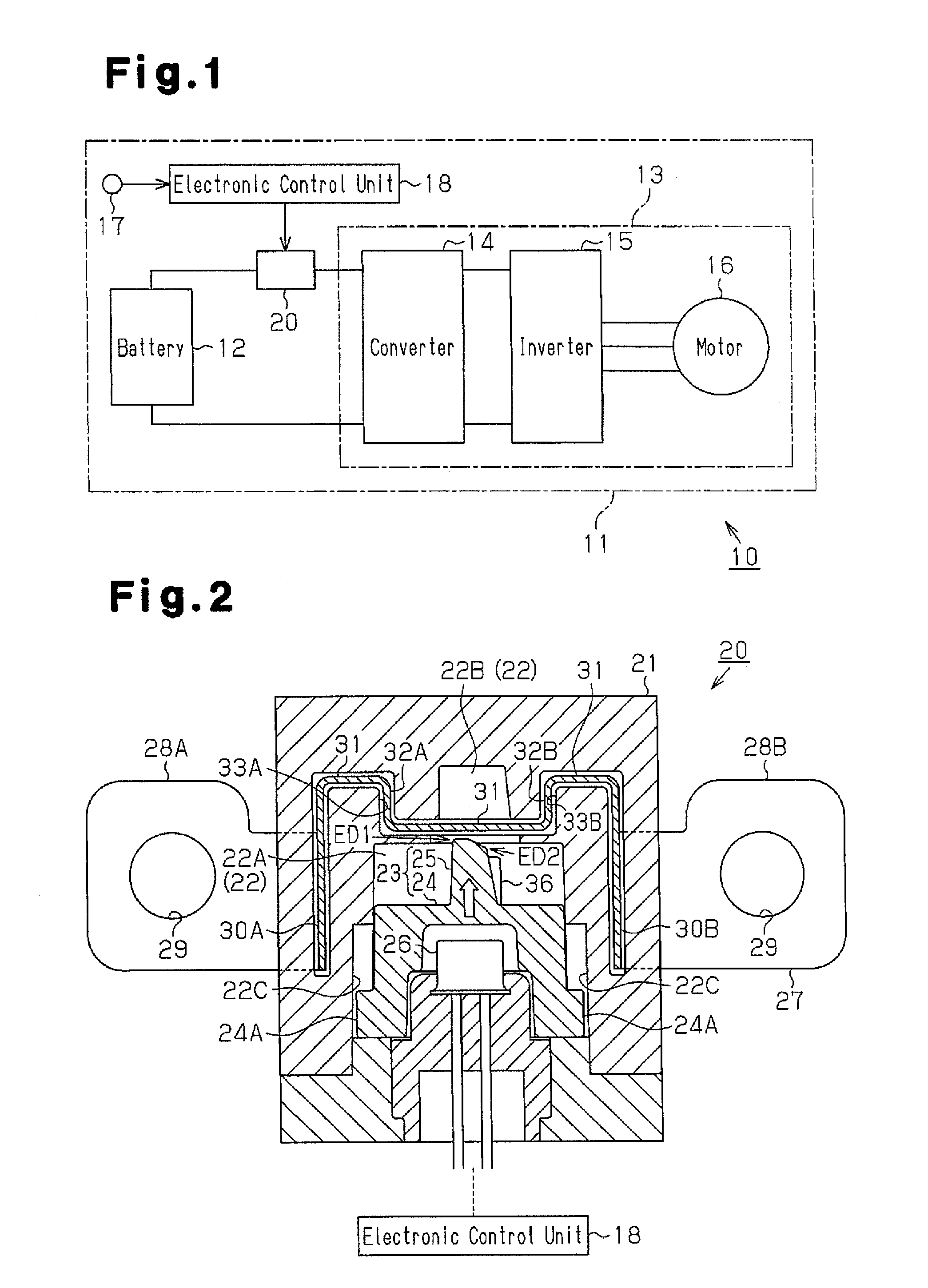
[0026]As shown in FIG. 1, the conduction breaking device 20 is employed in an electric circuit 11. The electric circuit 11 has a battery 12 and an electrical device 13. In the electric circuit 11, the battery 12 supplies electricity to the electrical device 13, to drive the electrical device 13. The electrical device 13 includes a converter 14, which raises the voltage of the electricity supplied by the battery 12, an inverter 15, which inverts the direct current electricity from the converter 14 to an alternating current electricity, and a motor 16, which is driven by the alternating current electricity from the inverter 15.

[0027]The electric circuit 11 is mounted on a vehicle 10. When the vehicle 10 is damaged due to, for example, a collision, the electrical device 13 may fail to operate properly or a current may leak from the electric circuit 11. Thus, the vehicle 10 i...


PUM


Abstract

A conduction breaking device includes a movable member accommodated in an accommodation chamber of a case. A cutter portion projects from an advancing side of the movable member in the moving direction. A gas generator is arranged on the trailing side of the movable member in the moving direction. A conduction member extends to connect a pair of external connection portions and includes a pair of base portions and a breakable portion. The base portions are located in the side wall of the case and extend along the moving direction of the movable member. The breakable portion is shaped to connect the base portions to each other and to block the advancing side of the movable member in the moving direction. Step portions are formed in the breakable portion. Engaging portions that are engageable with the step portions are formed in the case.

Description

BACKGROUND OF THE INVENTION[0001]The present invention relates to a conduction breaking device that breaks conduction between electrical devices through cutting of a conduction member with a cutter portion.[0002]Conventionally, for example, Japanese Laid-Open Patent Publication No. 2004-306946 discloses a conduction breaking device. The conduction breaking device is placed between electrical devices. When an abnormality occurs in the electrical devices, the conduction breaking device is activated to break the conduction between the electrical devices.[0003]FIG. 12 illustrates one such conduction breaking device. As shown in FIG. 12, an accommodation chamber 102 is defined in a case 101. A movable member 103 is movably accommodated in the accommodation chamber 102. The movable member 103 has a protruding cutter portion 104, which is located on the advancing side with respect to the moving direction of the movable member 103, that is, the direction indicated by the arrow in the drawin...

Claims


Application Information

Patent Timeline
IPC IPC(8): H02H3/02
CPCH01H39/006
Inventor FUKUYAMA, TAKAKISHIBAYAMA, KENJIOKADA, YASUSHI
Owner TOYODA GOSEI CO LTD
Why Eureka
Try Eureka