LED lamp

a technology of led lamps and led lamps, which is applied in the direction of semiconductor devices for light sources, lighting and heating apparatus, transportation and packaging, etc., can solve the problems of high heat generation, high power consumption of conventional incandescent lamps, and high heat dissipation, and achieve the effect of prolonging the service life of power modules

Inactive Publication Date: 2012-08-02
FIN CORE +1
View PDF3 Cites 47 Cited by
  • Summary
  • Abstract
  • Description
  • Claims
  • Application Information

AI Technical Summary

Benefits of technology

[0008]Accordingly, it is a primary objective of the present invention to provide an LED lamp having an LED, a power module, and a thermally insulating panel for insulating the heat generated by the LED from the power module, so as to extend the service life of the power module.
[0009]Another objective of the present invention is to provide an LED lamp having cooling fins each bending at a preset position thereof in a first direction and thereby bending at a preset included angle, and an elongate curved bend is disposed at a preset peripheral position of the plate-shaped cooling fin, to thereby reinforce the cooling fins and increase the heat-dissipating area of the cooling fins while still meeting the requirement of a uniform outer diameter.

Problems solved by technology

Conventional incandescent lamps are power-consuming, highly heat-generating, and relatively short-lived.
Not only do conventional incandescent lamps become environment-unfriendly in the present era of high-priced electricity supply, but the highly heat-generating conventional incandescent lamps are likely to end up with an accident, such as a fire caused by a short circuit.
Although the conventional LED lamp 1 is more power-saving and environment-friendly than conventional incandescent lamps, the LED unit 11 is also confronted with a problem with heat dissipation.
When operating for a long period of time, the control circuit 14 is likely to be compromised by the aging of components, such as electrolytic capacitors and integrated circuits (IC), which eventually causes damage to the components of the control circuit 14; as a result, the LED lamp 1 disadvantageously features a great increase in its failure rate and non-conforming rate and even a reduction in its service life.

Method used


Image

  • LED lamp
  • LED lamp
  • LED lamp

Examples


Embodiment Construction

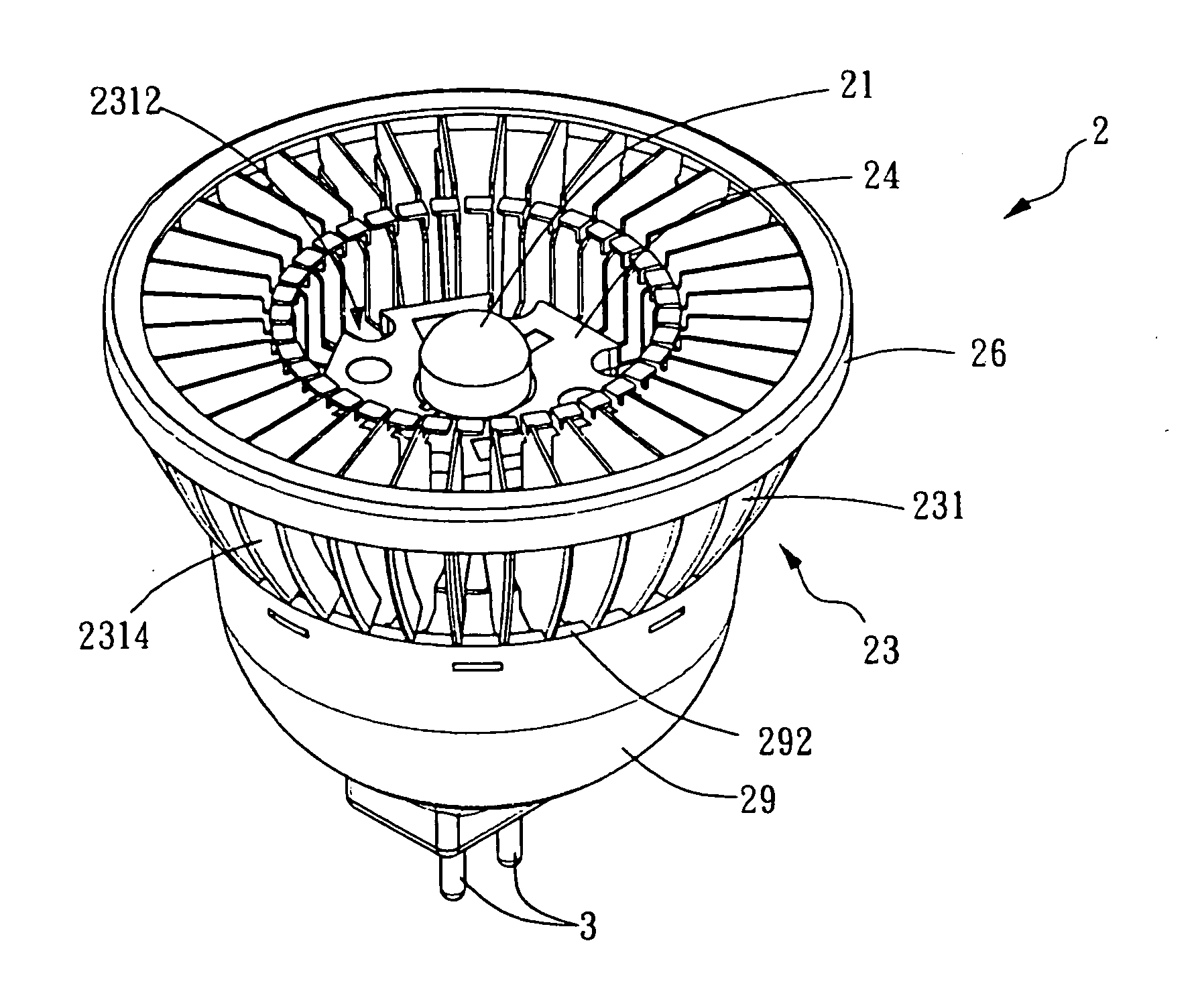
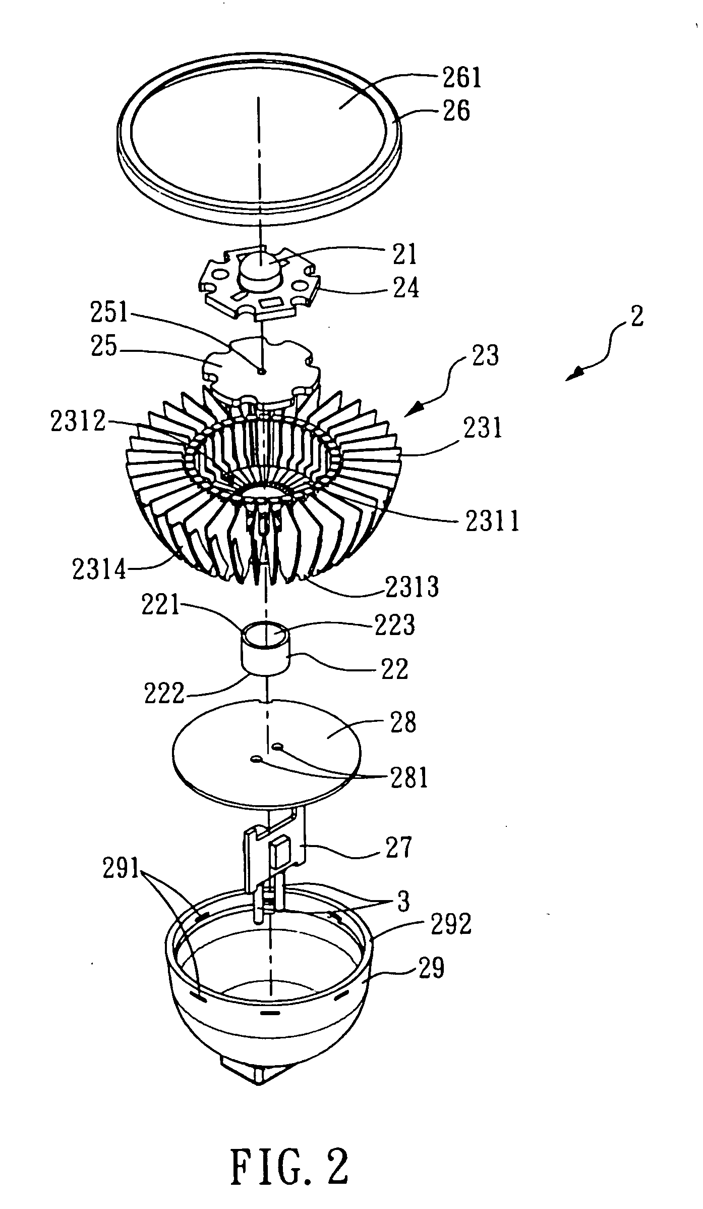
[0040]Referring to FIG. 2, FIG. 3 and FIG. 4, there are shown an exploded perspective view, an assembled perspective view, and a schematic cross-sectional view of an LED lamp 2 according to a first preferred embodiment of the present invention, respectively. As shown in FIG. 2, the

[0041]LED lamp 2 of the present invention comprises: at least an LED unit 21, a central post 22, a heat-dissipating module 23, a substrate 24, a carrying board 25, an annular protective cover 26, a power module 27, a thermally insulating panel 28, and a base 29.

[0042]The central post 22 is a pipe structure made of metal and hollowed out to have two ends in communication with each other. The central post 22 comprises a top end 221, a bottom end 222, and a through hole 223. The central post 22 is made of a highly thermally conductive metal, such as iron, copper, aluminum, silver, or gold, or an alloy thereof.

[0043]The heat-dissipating module 23 comprises a plurality of cooling fins 231 made of metal, arrange...


PUM


Abstract

An LED lamp includes at least an LED unit, a heat-dissipating module, a substrate, a power module, a base, and a thermally insulating panel. The heat-dissipating module includes a plurality of cooling fins arranged radially, spaced apart from each other, and connected annularly. The LED unit is disposed on and coupled to the substrate. The substrate is disposed above the heat-dissipating module. The base is a hollow casing for accommodating the power module and the thermally insulating panel, and is coupled to the heat-dissipating module. The thermally insulating panel is inserted into a groove disposed on an inner edge of the base and positioned between the heat-dissipating module and the power module. The thermally insulating panel is spaced apart from the heat-dissipating module by an air-filled gap of a preset distance to insulate the heat generated by the LED unit and further protect the power module.

Description

BACKGROUND OF THE INVENTION[0001]1. Field of the Invention[0002]The present invention relates to light-emitting diode (LED) lamps, and more particularly, to an LED lamp which has a light-emitting diode (LED), a base, a power module disposed in the base, a thermally insulating panel, a heat-dissipating module, and a preset gap between the thermally insulating panel and the heat-dissipating module, so as to further insulate the heat generated by the LED and prevent the power module from being overheated.[0003]2. Description of the Prior Art[0004]Among a wide variety of commercially available lamps, incandescent lamps always account for a constantly large market share. Conventional incandescent lamps are power-consuming, highly heat-generating, and relatively short-lived. Not only do conventional incandescent lamps become environment-unfriendly in the present era of high-priced electricity supply, but the highly heat-generating conventional incandescent lamps are likely to end up with ...

Claims


Application Information

Patent Timeline
Patent Type & Authority Applications(United States)
IPC IPC(8): F21V29/00
CPCF21K9/135F21K9/1375F21V3/00F21V29/89F21V29/20F21V29/773F21V29/86F21Y2101/02F21K9/23F21K9/232F21Y2115/10F21K9/00F21S2/005
Inventor WU, WEI CHUNG
Owner FIN CORE
Why Eureka
Try Eureka