Axial brush seal

a technology of axial brush seals and axial brushes, which is applied in the direction of machines/engines, stators, liquid fuel engines, etc., can solve the problems of imbalance between rotors and turbines, affecting critical speeds, and power turbines that do not have enough space for radial brush seals

Active Publication Date: 2012-08-02
GENERAL ELECTRIC CO
View PDF5 Cites 17 Cited by
  • Summary
  • Abstract
  • Description
  • Claims
  • Application Information

AI Technical Summary

Problems solved by technology

Their implementation in power turbines can be limited by their tendency to influence rotordynamics in the power turbines through frictional heating of the rotor body.
For example, non-uniform circumferential heating of the rotor can cause the rotor to bow introducing imbalance into the turbine affecting critical speeds.
In addition, certain power turbines may not have enough space for radial brush seals.

Method used


Image

  • Axial brush seal
  • Axial brush seal
  • Axial brush seal

Examples


Embodiment Construction

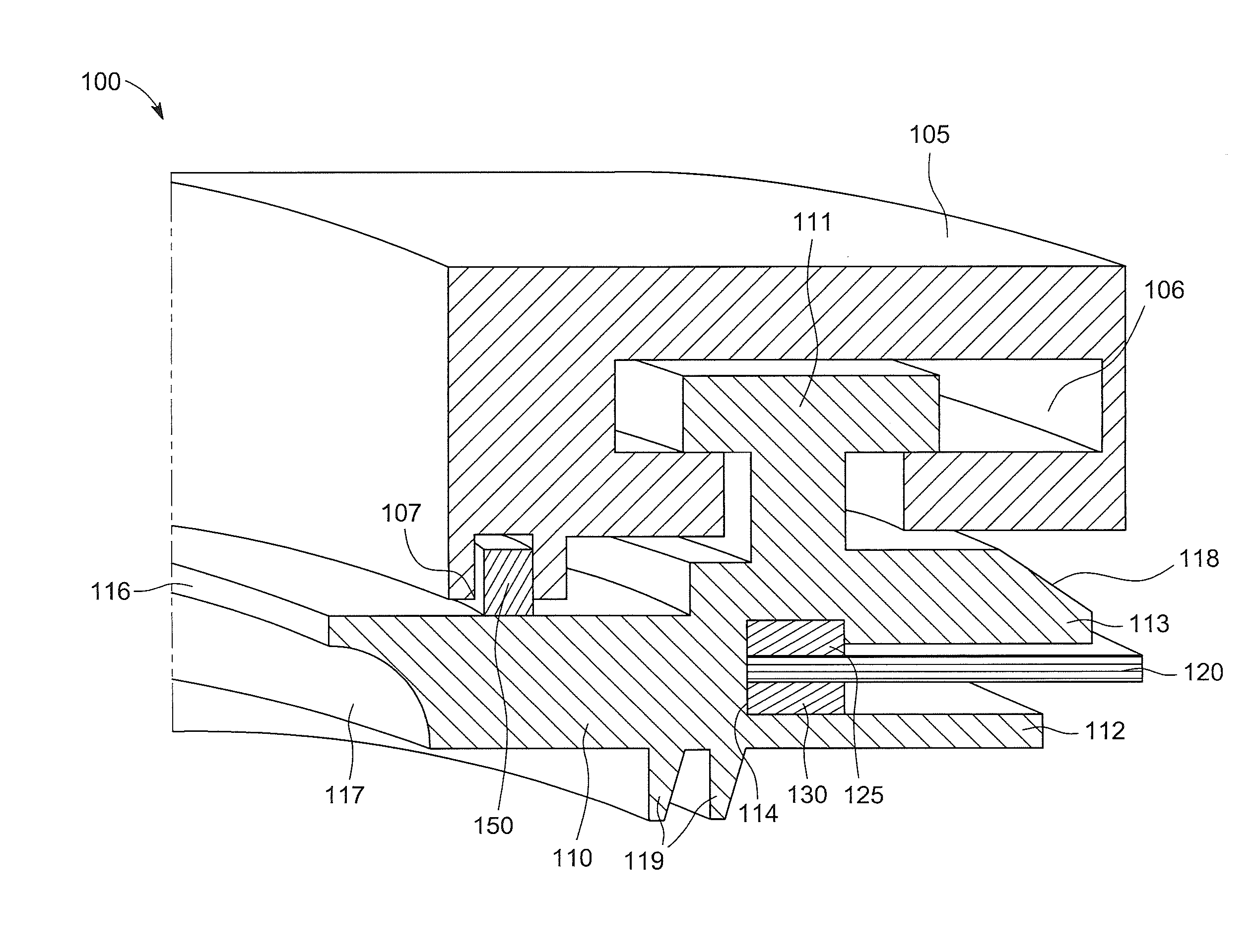
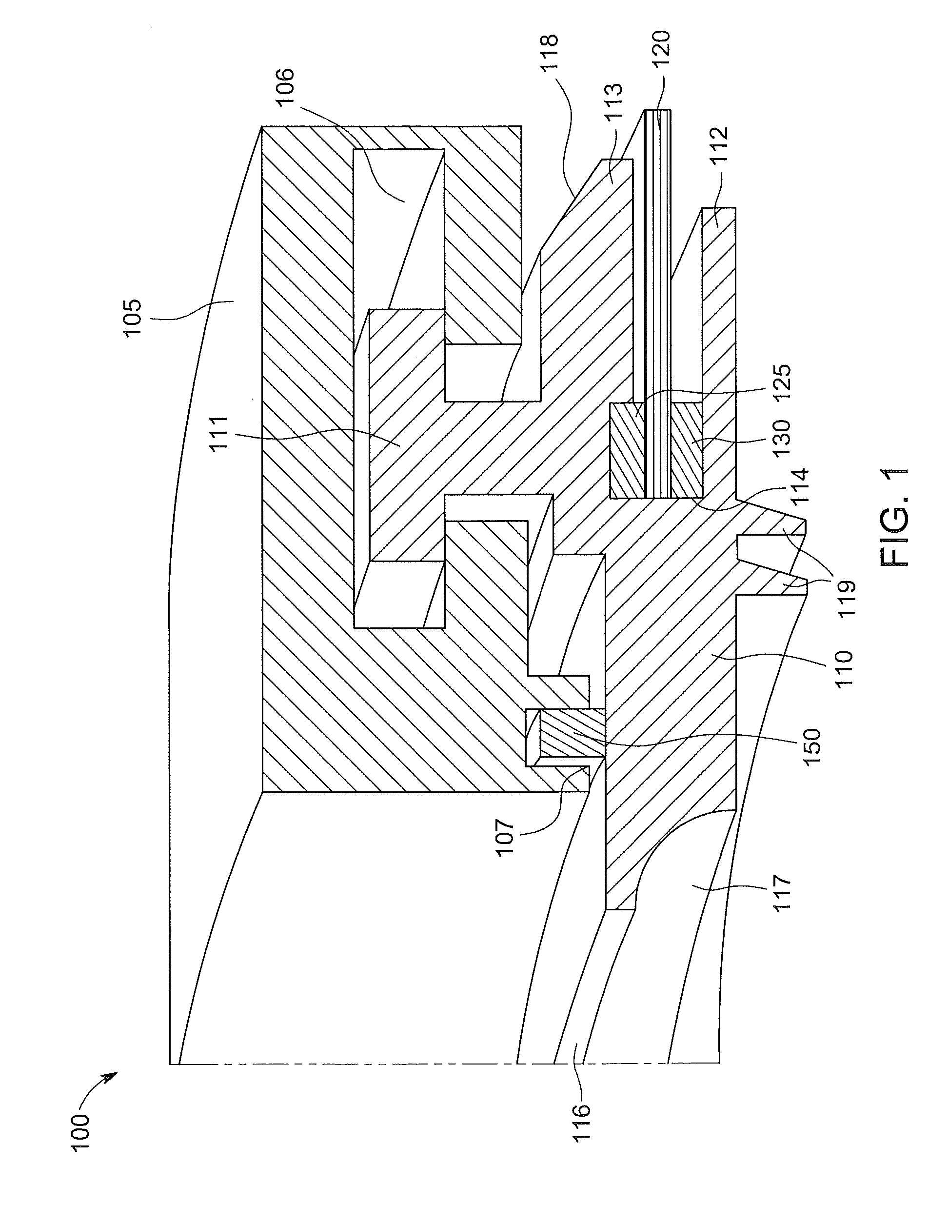
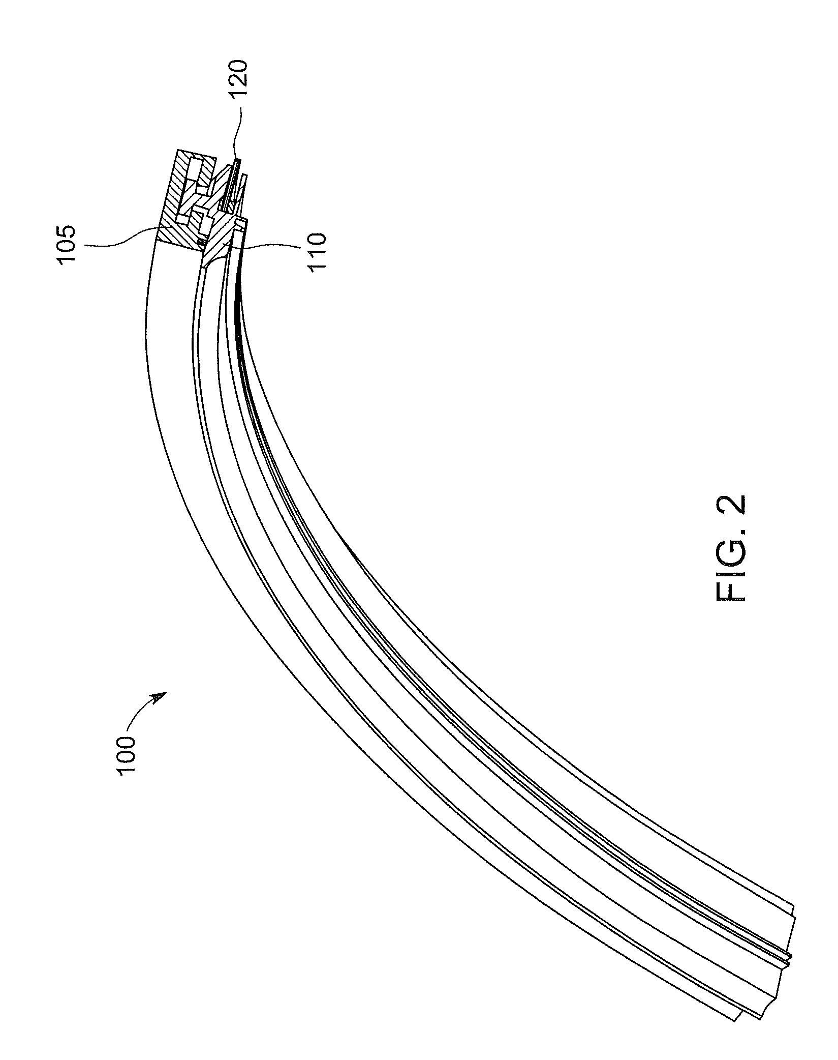
[0014]Exemplary embodiments described herein include floating axial brush seals. These seals can seal against wheel faces, thus avoiding frictional heating of the rotor body and eliminating effects on rotordynamics. The floating axial brush seals can be implemented with a combination of very high pressure drops in turbine wheel spaces across the seals (greater than or equal to 500 pounds per square inch differential (psid) (3.45 Newtons per square millimeter (N / mm2))) and large relative axial movements (+ / −0.5 inches (1.27 centimeters (cm))) between turbine rotating and stationary components. The floating axial brush seal has a structure that self-regulates to pressure changes in the wheel spaces at each stage of the power turbine. By adjusting to the axial position of the rotor and maintaining adequate bristle support to sustain high-pressure applications, the floating axial brush seals can enable the implementation of brush seals at every turbine stage.

[0015]Generally, a brush sea...


PUM


Abstract

A brush seal assembly for turbomachinery having a rotor can include a stationary seal component, a floating seal component coupled to the stationary seal component and circumferentially angled bristles arranged in a bristle pack, disposed in the floating seal component and extended axially with respect to the rotor.

Description

BACKGROUND OF THE INVENTION[0001]The subject matter disclosed herein relates to sealing structures in turbomachinery, and more particularly to floating axial brush seals.[0002]Radial brush seals are an established technology in turbomachinery. Their implementation in power turbines can be limited by their tendency to influence rotordynamics in the power turbines through frictional heating of the rotor body. For example, non-uniform circumferential heating of the rotor can cause the rotor to bow introducing imbalance into the turbine affecting critical speeds. In addition, certain power turbines may not have enough space for radial brush seals.[0003]What is needed is a brush seal that reduces rotor heating and can be implemented in a turbine with limited radial space.BRIEF DESCRIPTION OF THE INVENTION[0004]According to one aspect of the invention, a brush seal assembly for turbomachinery having a rotor is described. The assembly can include a stationary seal component, a floating sea...

Claims


Application Information

Patent Timeline
Patent Type & Authority Applications(United States)
IPC IPC(8): F04D29/08F16J15/44
CPCF01D11/001F02C7/28F05D2240/56F16J15/441F16J15/3288
Inventor SARAWATE, NEELESH NANDKUMARTURNQUIST, NORMAN ARNOLDADIS, WILLIAM EDWARDBARAN, ROBERT GERARDERDMENGER, RODRIGO RODRIGUEZPANNEKEET, ROBBERT CHRISTIAANPARKER, KEITH MICHAELZHENG, XIAOQING
Owner GENERAL ELECTRIC CO
Why Eureka
Try Eureka