
Heart rate variability sensor

a heart rate variability and sensor technology, applied in the field of medical methods, can solve the problems of ventricular fibrillation (vf) and sudden death, neurological damage or death, and algorithms that have been suggested are complicated and/or fail to produce reliable hrv values in clinical applications

Active Publication Date: 2012-08-02
LEV EL DIAGNOSTICS OF HEART DISEASE
View PDF4 Cites 32 Cited by
  • Summary
  • Abstract
  • Description
  • Claims
  • Application Information

AI Technical Summary

Benefits of technology

[0041]These, additional, and / or other aspects and / or advantages of the present invention are set forth in the detailed description which follows; possibly inferable from the detailed description, and / or learnable by practice of the present invention.

Problems solved by technology

Some of the algorithms that have been suggested however are complicated and / or fail to produce HRV values that are reliable in clinical applications.
VT is a potentially life-threatening arrhyhmia that may lead to ventricular fibrillation (VF) and sudden death.
A problem with ICD's however is that they sometimes respond to the arrhythmia too late, causing neurological damage or death.
Another problem is that the ICD electric shocks, even if appropriately delivered, are painful and often unexpected by the patient.
Yet another concern is simply the risk that is always present for a procedure that involves surgery.
These drugs however are costly and have potent side effects.
The drawbacks of available therapies suggest the importance of obtaining an accurate diagnosis of a patient's post AMI risk for VT / VF.
A patient that is wrongly diagnosed as low risk and that accordingly doesn't receive an ICD or drug treatment has a high likelihood of experiencing a fatal heart attack Conversely, a patient that is wrongly diagnosed as high risk will experience some level of pain, trauma, cost, and / or surgical risk if implanted with an ICD or prescribed a drug unnecessarily.
However, there continues to be an excessive variation among different practitioners in the effective rate of ICD implantation and appropriate drug therapy, in part due to inadequate risk stratification.

Method used


Image

  • Heart rate variability sensor
  • Heart rate variability sensor
  • Heart rate variability sensor

Examples


Embodiment Construction

[0053]Reference will now be made in detail to embodiment(s) of the present invention, examples of which are illustrated in the accompanying drawings, wherein like reference numerals refer to the like elements throughout. The embodiment(s) is / are described below to explain the present invention by referring to the figures.

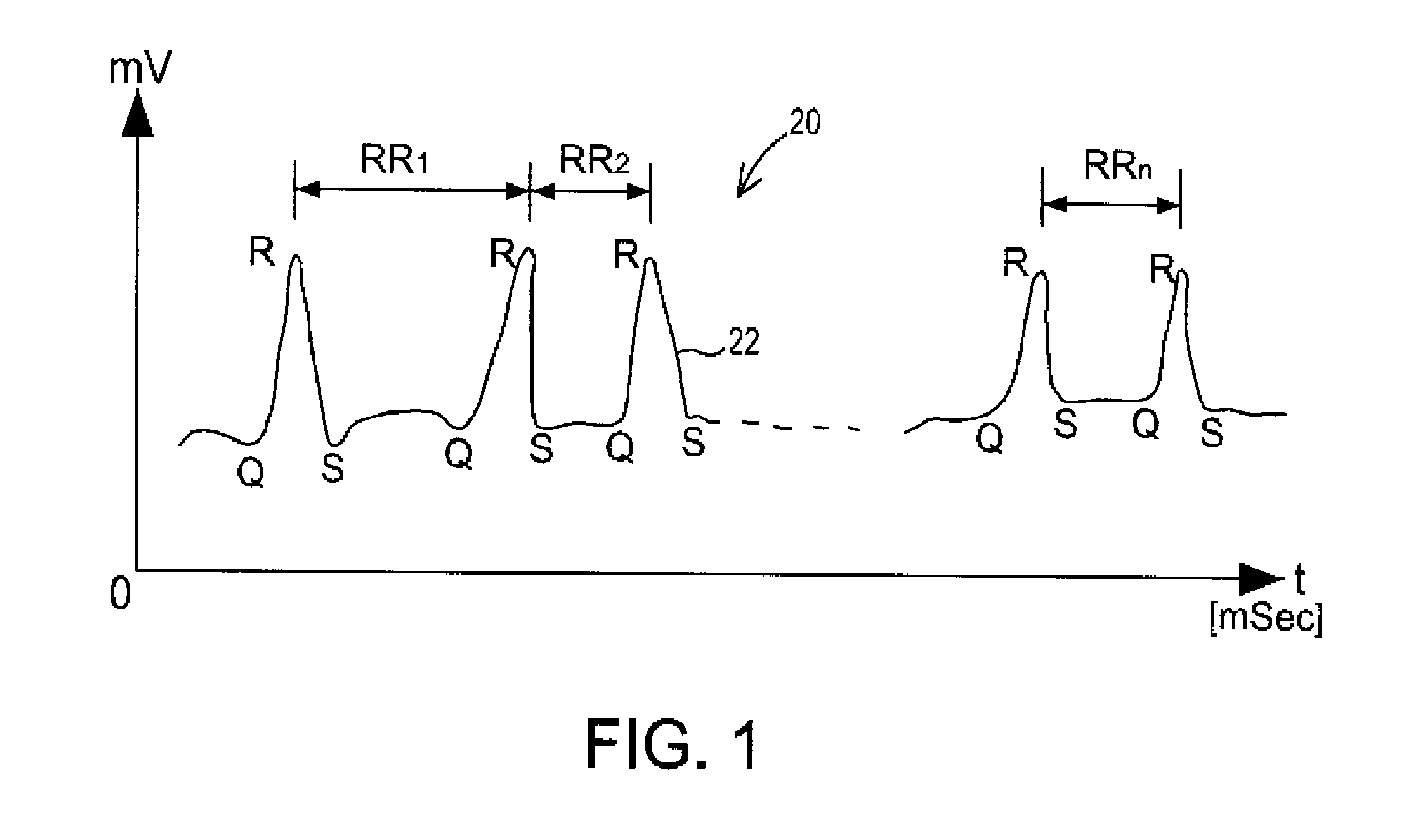
[0054]Referring to FIG. 1, there is shown a graphic illustration of a heartbeat wave or series of waves 20, as detected by an electrocardiograph (ECG) or similar device. A “beat-to-beat interval” is the time between equivalent points on adjacent waveforms. As noted above, by convention each wave contains standard reference points “QRS”. Accordingly, heartbeat waves 20 may be defined as a series of RR or peak intervals, as shown in the figure by intervals RR1, RR2, and RRn. It is to be appreciated that heartbeat intervals could also be measured with respect to any other equivalent points on the wave, such as the points “Q” and “S”, for example. For convenient referen...


PUM


Abstract

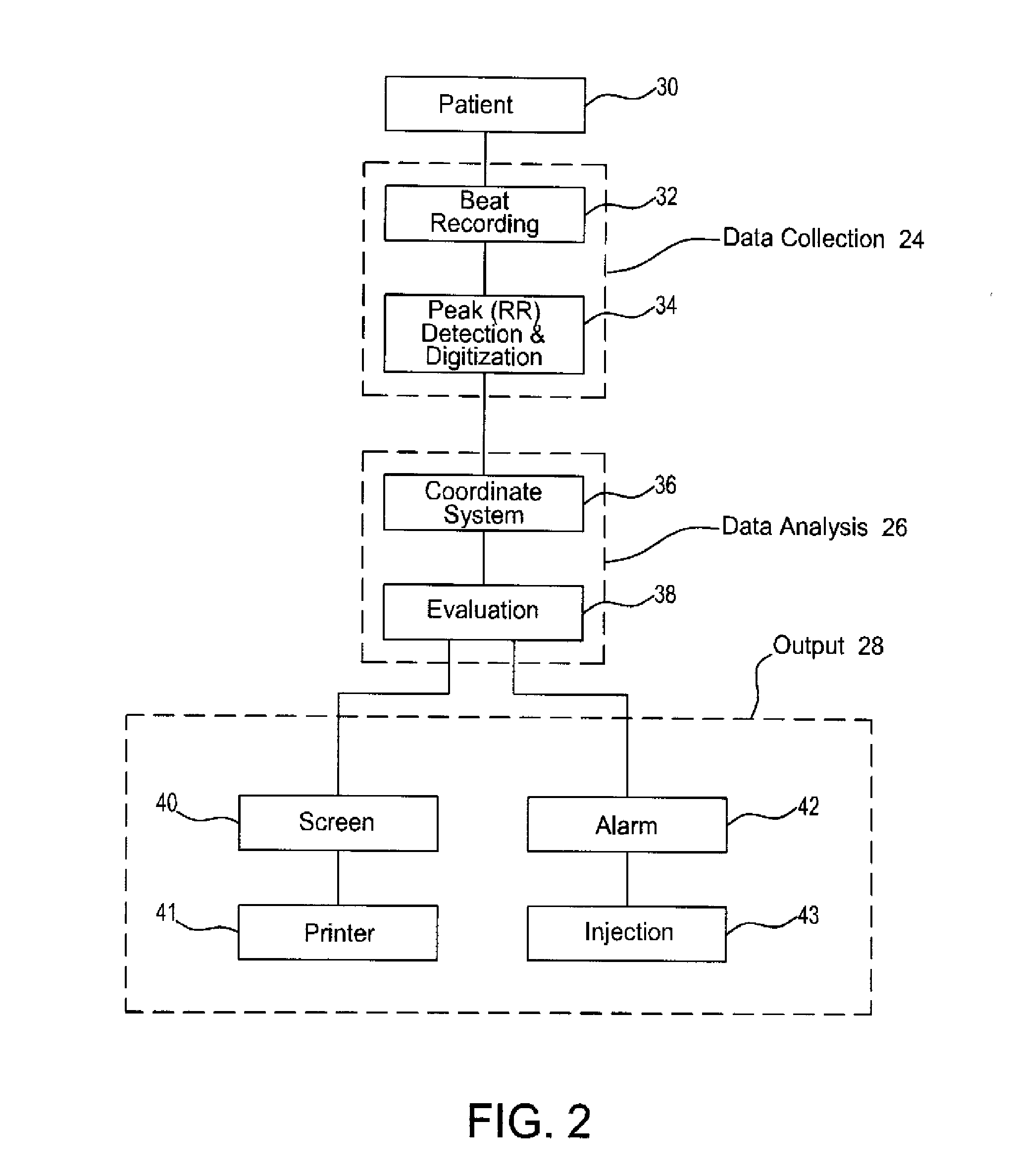
A system for measuring heart rate variability (HRV) comprising 3 sub-systems: a data collection sub-system, a data analysis sub-system, and an output sub-system. A patient is connected to a heart monitoring device such as an ECG and the data collection sub-system records the patients heart beats, and an ECG chart is produced from which the patient's HRV value is derived by the data analysis sub-system. The present invention obtains the HRV value through calculation of a new parameter called relative density (RD). In accordance with the inventive method, data points are generated from the peak interval data of measured heart beats and the HRV relative density parameter (RD) is calculated by correlation between two subsets of data points.

Description

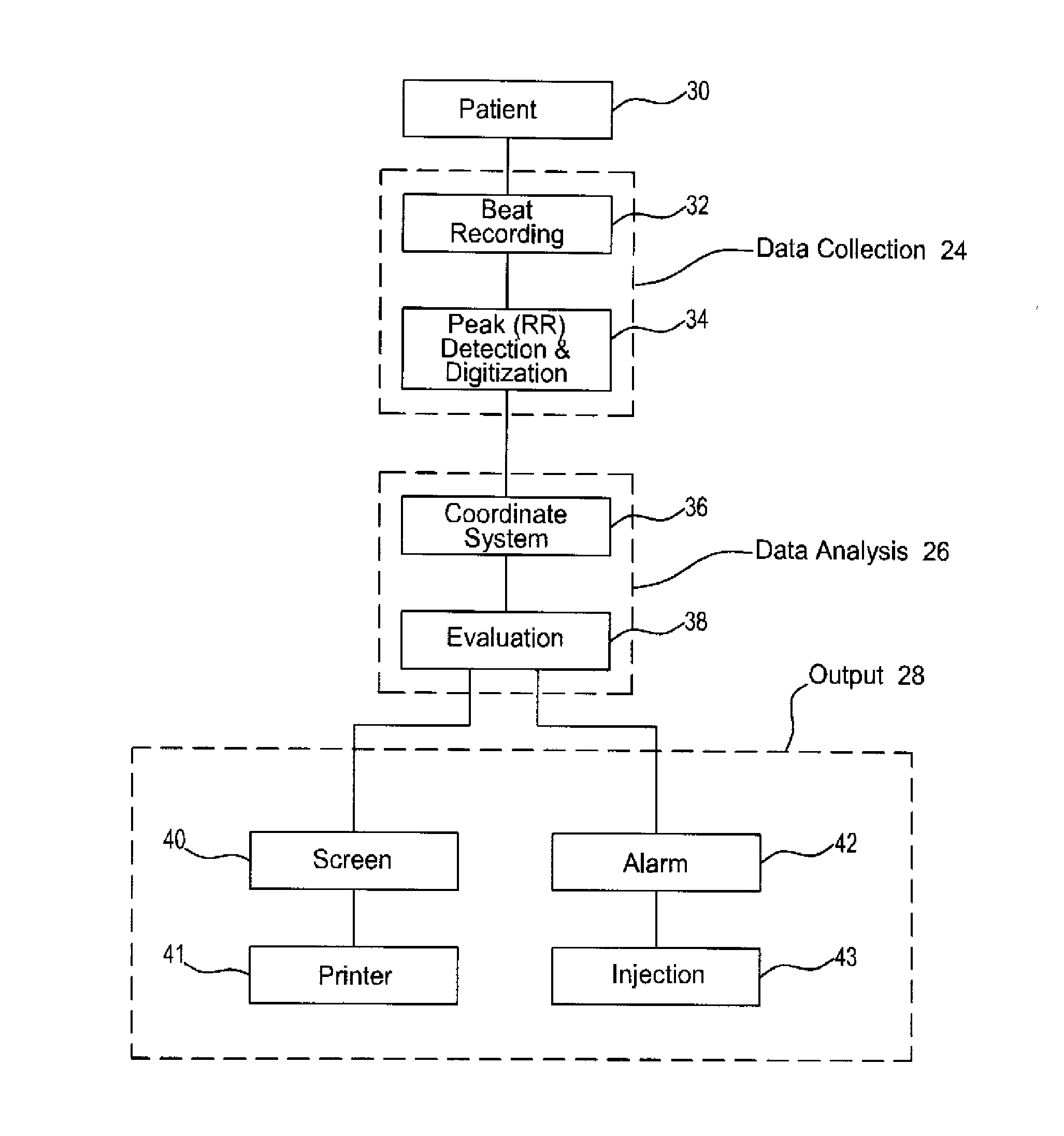
BACKGROUND[0001]1. Technical Field[0002]Embodiments of the present invention relate generally to medical methods and, more particularly, but not exclusively, to a method for measuring heart rate variability (HRV)[0003]2. Description of Related Art[0004]Heart rate variability (HRV) is a well-known characteristic of heart function, and is a measure of variation in heart rate experienced by a particular patient.[0005]HRV is usually measured as the time (in milliseconds) between successive heartbeats This time period is also known as the “beat-to-beat interval”, and is the inverse of the instantaneous heart rate expressed in beats per second. FIG. 1 shows a standard ECG display of a series of heartbeats. It can be seen that each heartbeat appears as a wave, and that each wave in the series has points in common designated “Q”, “R”, and “S” The point “R” is the highest peak and most visually distinguishable part of the wave, and therefore the easiest point from which to measure HRV. Accor...

Claims


Application Information

Patent Timeline
IPC IPC(8): A61B5/0456A61N1/00A61B5/044A61B5/0432A61B5/352A61B5/363
CPCA61B5/02405A61B5/0452A61N1/3621A61N1/3702A61B5/0464A61N1/3925A61N1/3962A61B5/7275A61B5/0245A61N1/37258G16H40/60A61N1/39622A61B5/349A61B5/363
Inventor LEVITAN, JACOBKOBO, ROI
Owner LEV EL DIAGNOSTICS OF HEART DISEASE
Learn More