
Energy absorber and method for setting a stiffness of an energy absorber

a technology of energy absorber and energy absorber, which is applied in the field of energy absorber, can solve the problems of low stiffness, reduced stiffness, and extension of the crumple zone of the motor vehicle, and achieves the effects of high stiffness, low stiffness, and high stiffness

Active Publication Date: 2012-08-02
ROBERT BOSCH GMBH
View PDF3 Cites 4 Cited by
  • Summary
  • Abstract
  • Description
  • Claims
  • Application Information

AI Technical Summary

Benefits of technology

[0007]In accordance with the present invention, an implementation of an adaptive energy absorber or an adaptive crash box having an integrated decision sensor system is provided. A part of the energy absorber may have an adjustable absorption structure, and another part may have a sensing unit for regulating the stiffness of the absorption structure. This adaptivity allows rapid stiffening, which may be switched on for a defined time, of the front vehicle section, and therefore a shortened design of the front vehicle section with identical protective action for the occupants. This results in a reduction of the weight of the vehicle, which in turn has a positive effect on the CO2 balance of the vehicle. The energy absorber according to the present invention is independent of a predictive sensor system and therefore may be integrated into the vehicle independently thereof.
[0011]In this case, the sensor may be situated in the first absorption element. In this way, the sensor may be integrated into a space-saving and protected way in the energy absorber.
[0013]According to one specific embodiment, the second absorption element may have a first element and a second element. The low stiffness may result through friction between the first element and the second element. Therefore, the second absorption element may be a friction element, which is designed to dissipate at least a part of the impact energy by friction.
[0017]Furthermore, the present invention provides an example control unit, which is designed to carry out or implement the steps of the method according to the present invention. An object on which the present invention is based may also be achieved rapidly and efficiently by this embodiment variant of the present invention in the form of a control unit.

Problems solved by technology

The bull bar is extendable and may cause an extension of the crumple zone of the motor vehicle in case of crash.
In addition, deformation elements are used, which may reduce their stiffness especially to improve pedestrian protection.
The low stiffness may result through friction between the first element and the second element.

Method used


Image

  • Energy absorber and method for setting a stiffness of an energy absorber
  • Energy absorber and method for setting a stiffness of an energy absorber
  • Energy absorber and method for setting a stiffness of an energy absorber

Examples


Embodiment Construction

[0027]In the following description of preferred exemplary embodiments of the present invention, identical or similar reference numerals are used for similarly acting elements shown in the various figures, a repeated description of these elements being omitted.

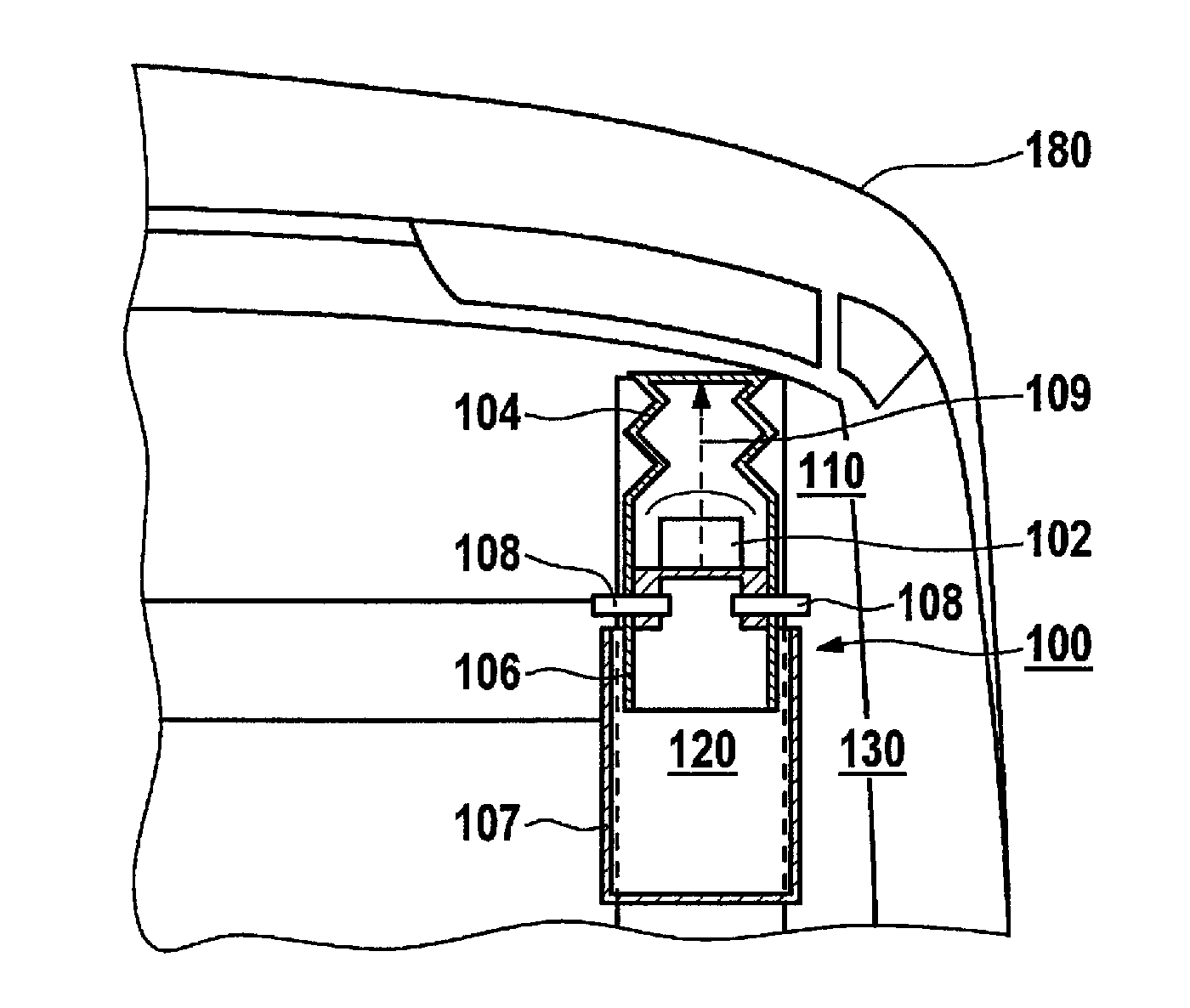
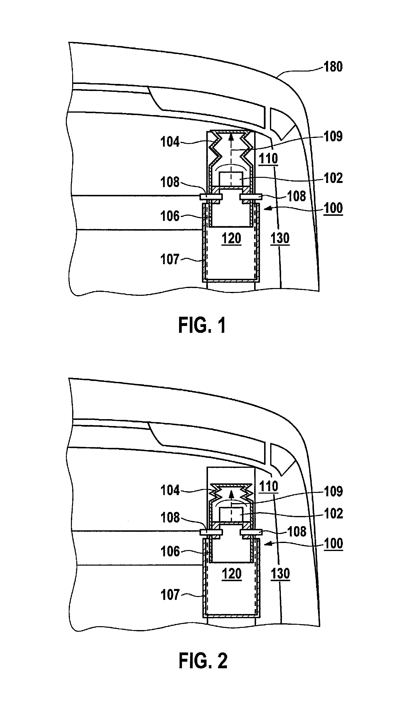
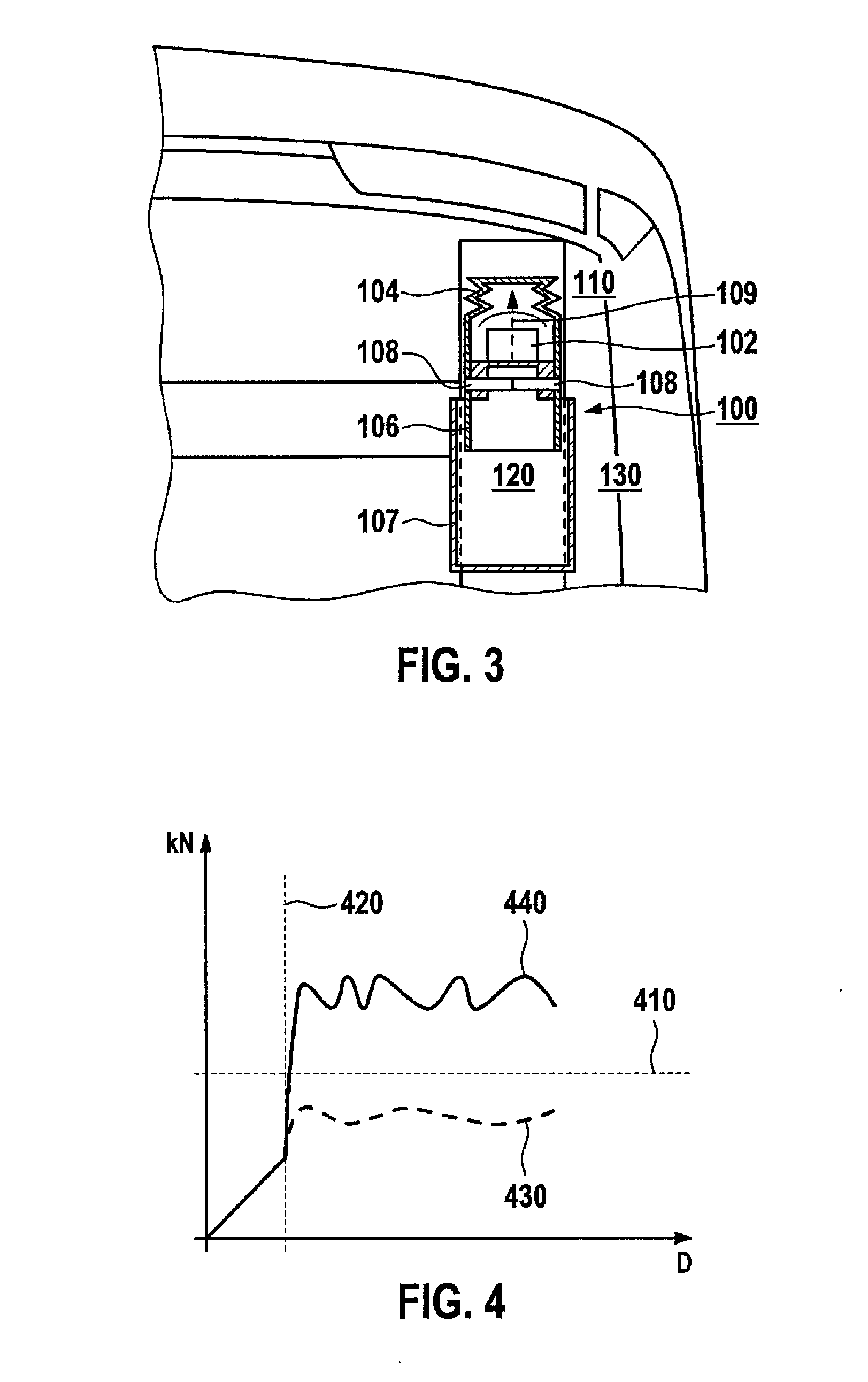
[0028]FIG. 1 shows a view of an energy absorber 100 according to an exemplary embodiment of the present invention. Energy absorber 100 may be situated in a vehicle and may include a sensor 102, a first absorption element 104 having a first stiffness, a second absorption element 106, 107 having a second stiffness, and a setting element 108. The first stiffness may be less than the second stiffness. According to the exemplary embodiment shown in FIG. 1, sensor 102 may be situated in first absorption element 104. Sensor 102 may be designed to detect a deformation 109 of first absorption element 104, for example, as a result of an impact of an object on the vehicle, and to provide the energy or force acting on the energy absorber t...


PUM


Abstract

An energy absorber for a vehicle is described, which includes a sensor integrated into the energy absorber, which is designed to detect an impact magnitude acting on the energy absorber and to provide information about the impact magnitude. Furthermore, the energy absorber includes at least one setting element, which is designed to set a stiffness of the energy absorber in response to the information about the impact magnitude.

Description

FIELD OF THE INVENTION[0001]The present invention relates to an energy absorber, a method for absorbing an impact energy, a control unit, and a computer program product.BACKGROUND INFORMATION[0002]German Patent Application No. DE 198 52 959 A1 describes a system of a bull bar on a motor vehicle bow, which is supported on load-bearing parts of the motor vehicle body using rigid rod profiles. The bull bar is extendable and may cause an extension of the crumple zone of the motor vehicle in case of crash.[0003]Furthermore, impact absorbers (crash absorbers), e.g., in the form of crash boxes are used in the field of impact absorption (crash absorption), which have a defined stiffness. Crash boxes having defined stiffness are currently primarily used to meet demands of AZT crashes. Adaptive crash boxes are also used, which may chane their stiffness depending on the situation, on the basis of a surroundings sensor system or pre-crash sensor system.[0004]In addition, deformation elements ar...

Claims


Application Information

Patent Timeline
Patent Type & Authority Applications(United States)
IPC IPC(8): B60G17/018
CPCB60R2019/007B60R19/34
Inventor FREIENSTEIN, HEIKOWEEBER, KAIKOENNING, MARKUS
Owner ROBERT BOSCH GMBH
Learn More