Wireless telemetry system for a turbine engine

a technology of telemetry system and turbine engine, which is applied in the direction of error detection/correction, instruments, digital computers, etc., can solve the problems of not being compatible with turbine blade sections that incorporate seal plates, the above-described rotating antenna assembly may not be used with seal plates, and the seal plate would interfere with the transmission of signals from the antenna

Inactive Publication Date: 2012-08-02
SIEMENS ENERGY INC
View PDF2 Cites 32 Cited by
  • Summary
  • Abstract
  • Description
  • Claims
  • Application Information

AI Technical Summary

Problems solved by technology

While the above-described rotating antenna assembly 308 works for certain turbine engine designs, it may not be compatible with turbine blade sections that incorporate seal plates.
However, the above-described rotating antenna assembly may not be used with seal plates.
There is insufficient space between the seal plate and face of the root blade, and if the antenna assembly is capable of being mounted to the blade root face, the seal plate would interfere with transmission of signals from the antenna.

Method used


Image

  • Wireless telemetry system for a turbine engine
  • Wireless telemetry system for a turbine engine
  • Wireless telemetry system for a turbine engine

Examples


Embodiment Construction

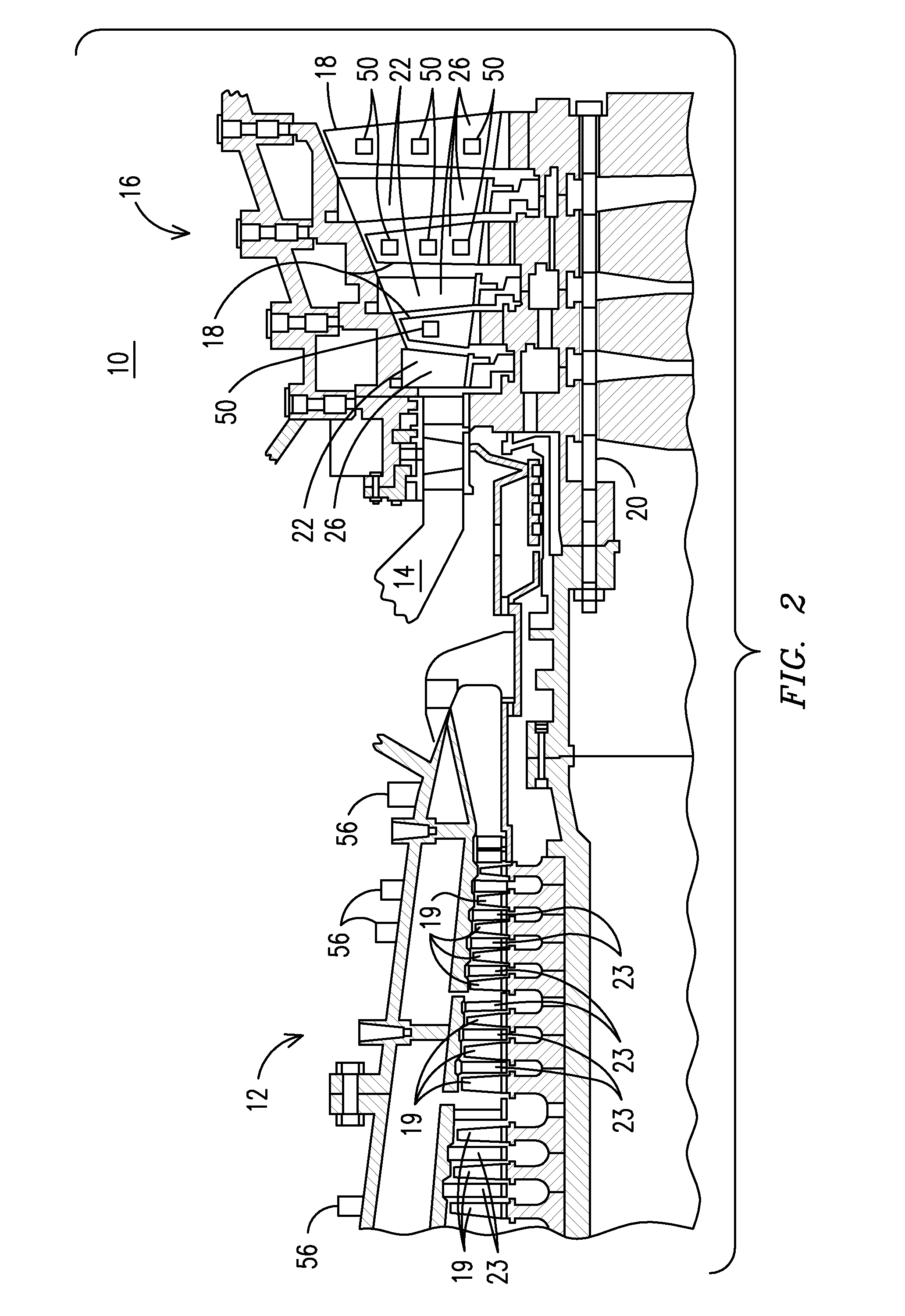
[0025]FIG. 2 illustrates an exemplary combustion turbine 10 such as a gas turbine used for generating electricity. Embodiments of the invention may be used with combustion turbine 10 or in numerous other operating environments and for various purposes. Combustion turbine 10 includes a compressor 12, at least one combustor 14 (broken away) and a turbine 16. Compressor 12, combustor 14 and turbine 16 are sometimes referred to collectively as a gas or combustion turbine engine 10. Turbine 16 includes a plurality of rotating blades 18, secured to a rotatable central shaft 20. A plurality of stationary vanes 22 are positioned between blades 18, with vanes 22 being dimensioned and configured to guide air over blades 18. Blades 18 and vanes 22 will typically be made from nickel-based alloys, and may be coated with a thermal barrier coating (“TBC”) 26, such as yttria-stabilized zirconia. Similarly, compressor 12 includes a plurality of rotating blades 19 positioned between respective vanes ...


PUM


Abstract

A telemetry system for use in a combustion turbine engine (10) having a compressor (12), a combustor and a turbine (16) and includes a sensor (118) in connection with a turbine blade (111) or vane (23). A transmitter assembly (117) includes a telemetry transmitter circuit / transceiver may be affixed on a turbine blade (111) or seal plate (115) proximate the turbine blade with a first connecting material (119) deposited on the turbine blade (111) for routing electronic data signals, indicative of a condition of the turbine blade (111), from the sensor (118) to the telemetry transmitter circuit / transceiver. An induction power system for powering the telemetry transmitter circuit / transceiver may include a rotating data antenna (116) affixed to the seal plate (115) with an electrical connection (122) between the telemetry transmitting circuit / transceiver for routing electronic data signals from the telemetry transmitter circuit / transceiver to the rotating data antenna (119).

Description

FIELD OF THE INVENTION[0001]The present invention relates generally to monitoring operating environments and in particular to instrumented components and telemetry systems enabled for wirelessly transmitting electronic data indicative of individual component condition within an operating environment such as that of a combustion turbine engine.BACKGROUND OF THE INVENTION[0002]A wireless telemetry system for a turbine combustion is disclosed in U.S. application Ser. No. 11 / 936,936, which is incorporated herein by reference. As disclosed therein, a high temperature wireless telemetry system may be powered by induced RF energy generated by air gap transformers including a transformer primary induction coil assembly that is stationary and a secondary induction coil assembly that rotates. The telemetry system includes at least one sensor deposited on a component such as a turbine blade. A telemetry transmitter circuit is affixed to the turbine blade and a connecting material is deposited ...

Claims


Application Information

Patent Timeline
Patent Type & Authority Applications(United States)
IPC IPC(8): G06F15/00
CPCF01D17/20F01D17/02
Inventor MITCHELL, DAVID J.SUBRAMANIAN, RAMESHSCHILLIG, CORAKULKARNI, ANAND A.JONNALAGADDA, VINAYACAR, BULENTNELLIAN, SANKARWILLIAMS, JAMES P.ROESCH, EDWARD R.
Owner SIEMENS ENERGY INC
Why Eureka
Try Eureka